Substrate treatment apparatus and substrate treatment method

Active Publication Date: 2010-09-30
DAINIPPON SCREEN MTG CO LTD
View PDF12 Cites 31 Cited by
  • Summary
  • Abstract
  • Description
  • Claims
  • Application Information

AI Technical Summary

Benefits of technology

[0043]The opposing member is held in a vertically movable manner by the support member. The opposing member receives the move-away force occurring due to the contact between the treatment liquid film and the opposing member to be moved upward relative to the support member. The move-away force acting on the opposing member, i.e., the lift force received from the treatment liquid film by the opposing member, increases as the opposing member approaches the upper surface of the substrate. Therefore, the opposing member is retained at a position at which a force acting toward the upper surface of the substrate (a move-toward force such as a gravitational force acting on the opposing member) and the move-away force acting on the opposing member are balanced. Therefore, the opposing member can be opposed to and spaced a minute distance from the upper surfac

Problems solved by technology

This increases the amount of the treatment liquid required for the treatment of the single substrate, thereby correspondingly increasing the treatment costs.
However, there is a possibility that the substrate vertically wobbles during the rotation of the substrate.
Even if an attempt is made to place the opposing plate in closely opposed relation to the substrate, there is a limitation in the distance between the opposing plate and the substrate.
More specifically, an attempt to maintain the distance between the opposing plate and the substrate to several tenths of millimeters is likely to fail due to the vertical wobbling of the substrate.
As a result of variations in the distance between the opposing plate and the substrate, the thin liquid film present between

Method used


Image

  • Substrate treatment apparatus and substrate treatment method
  • Substrate treatment apparatus and substrate treatment method
  • Substrate treatment apparatus and substrate treatment method

Examples


first embodiment

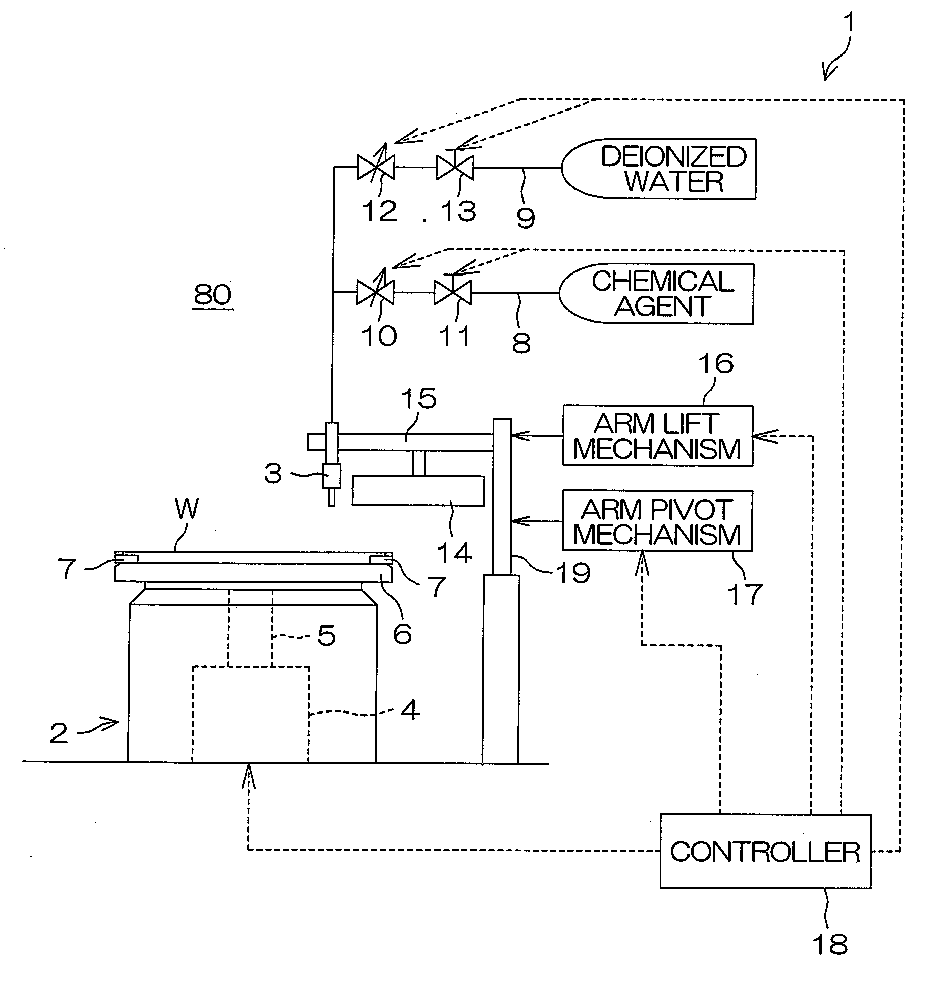
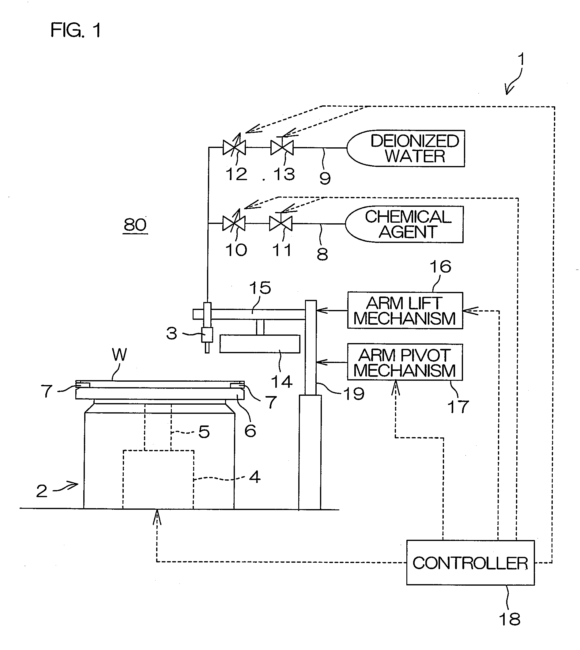
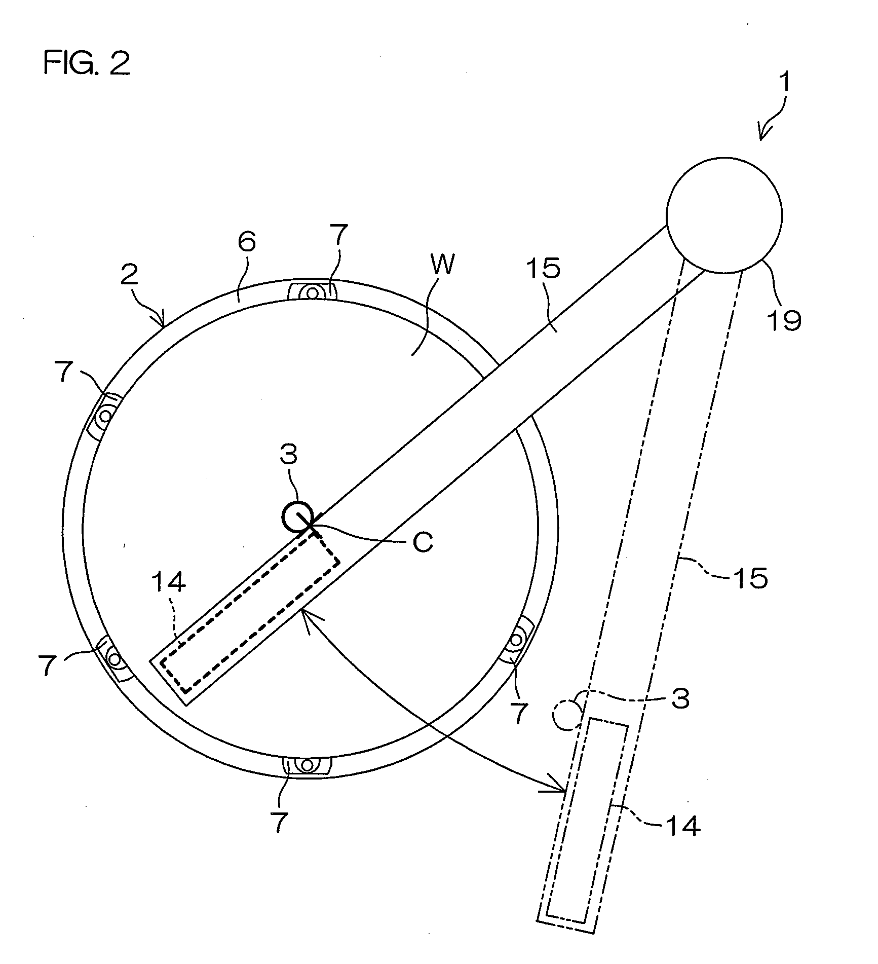
[0064]FIG. 1 is a diagram schematically showing the construction of a substrate treatment apparatus 1 according to one embodiment (first embodiment) of the present invention. FIG. 2 is a plan view showing the schematic construction of the substrate treatment apparatus 1.

[0065]The substrate treatment apparatus 1 is of a single substrate treatment type for treating a front surface of a semiconductor wafer (hereinafter referred to simply as “wafer”) W as an exemplary substrate with a treatment liquid (e.g., a chemical agent and deionized water).

[0066]The substrate treatment apparatus 1 includes a spin chuck (substrate holding unit) 2 which horizontally holds and rotates the wafer W, and a nozzle 3 which supplies the treatment liquid to an upper surface (front surface) of the wafer W held by the spin chuck 2. The spin chuck 2 and the nozzle 3 are provided in a treatment chamber 80 defined by a partition wall (not shown).

[0067]The spin chuck 2 includes a motor (rotating unit) 4, a spin s...

third embodiment

[0120]FIG. 11 is a diagram schematically showing the construction of a substrate treatment apparatus 201 according to further another embodiment (third embodiment) of the present invention.

[0121]The substrate treatment apparatus 201 is of a single substrate treatment type for performing a cleaning process for removing a contaminant from a wafer W with the use of a treatment liquid.

[0122]The substrate treatment apparatus 201 includes a spin chuck (substrate holding unit) 203 which horizontally holds and rotates the wafer W, a chemical agent nozzle 204 which spouts a chemical agent toward a front surface (upper surface) of the wafer W held by the spin chuck 203, and a deionized water nozzle 205 which supplies deionized water to the front surface of the wafer W held by the spin chuck 203. The spin chuck 203, the chemical agent nozzle 204 and the deionized water nozzle 205 are provided in a treatment chamber 202 defined by a partition wall (not shown).

[0123]The spin chuck 203 includes a...

fourth embodiment

[0170]FIG. 17 is a perspective view schematically showing the construction of a substrate treatment apparatus 240 according to still another embodiment (fourth embodiment) of the present invention. FIG. 18 is a sectional view schematically showing the construction of the substrate treatment apparatus 240 shown in FIG. 17.

[0171]The substrate treatment apparatus 240 of the fourth embodiment shown in FIGS. 17 and 18 differs from the substrate treatment apparatus 201 of the third embodiment in that a disk-shaped opposing plate 241 is provided instead of the bar-shaped opposing bar 220 as the opposing member.

[0172]The opposing plate 241 includes a cylindrical fixture portion 242 (see FIG. 18) provided about the rotation center axis of the wafer W, and a disk-shaped disk portion 243 having a center aligning with the rotation center of the wafer W. The fixture portion 242 is provided instead of the fixture portion 230 of the third embodiment, and fitted around and fixed to the outlet pipe ...


PUM


Abstract

A substrate treatment apparatus includes: a substrate holding unit which horizontally holds a substrate; a substrate rotating unit which rotates the substrate held by the substrate holding unit about a vertical axis; a treatment liquid supplying unit which supplies a treatment liquid to an upper surface of the substrate held by the substrate holding unit; an opposing member to be located in opposed spaced relation to the upper surface of the substrate held by the substrate holding unit in contact with a film of the treatment liquid formed on the upper surface of the substrate so as to receive a lift force from the liquid film; a support member which supports the opposing member; and an opposing member holding mechanism which causes the support member to hold the opposing member in a vertically relatively movable manner.

Description

BACKGROUND OF THE INVENTION[0001]1. Field of the Invention[0002]The present invention relates to a substrate treatment apparatus and a substrate treatment method for treating a substrate with a treatment liquid. Examples of the substrate to be treated include semiconductor wafers, substrates for liquid crystal display devices, substrates for plasma display devices, substrates for FED (Field Emission Display) devices, substrates for optical disks, substrates for magnetic disks, substrates for magneto-optical disks and substrates for photo masks.[0003]2. Description of Related Art[0004]In production processes for a semiconductor device and a liquid crystal display device, a substrate such as a semiconductor wafer or a glass substrate for the liquid crystal display device is treated with a treatment liquid. A substrate treatment apparatus of a single substrate treatment type adapted to treat a single substrate at a time includes, for example, a spin chuck which horizontally holds and r...

Claims


Application Information

Patent Timeline
IPC IPC(8): B05C11/08B05D3/12
CPCH01L21/67051H01L21/6715B05B13/0228B05C11/044B05C11/023B05C5/0208H01L21/67017H01L21/6708H01L21/68792
Inventor HASHIMOTO, KOJI
Owner DAINIPPON SCREEN MTG CO LTD
Why Eureka
Try Eureka