
Safety Apparatus and Protection Method of Secondary Battery for Electric Vehicle Using Switch

a secondary battery and safety apparatus technology, applied in secondary cells, battery service/maintenance, cell components, etc., can solve the problems of explosion and fire, increase the internal pressure of the battery, and rapid increase of the internal pressure and temperature of the battery, so as to prevent explosion and fire, protect the secondary battery, and prevent the human body.

Active Publication Date: 2010-09-30
SK ON CO LTD
View PDF6 Cites 27 Cited by
  • Summary
  • Abstract
  • Description
  • Claims
  • Application Information

AI Technical Summary

Benefits of technology

[0031]The safety apparatus and the protection method of the secondary battery for use in electric vehicle using the switch according to the present invention can safely protect destruction of the secondary battery caused by overcharge, short-circuit, reverse-connection and heat exposure of the secondary battery.
[0032]Further, there is an advantage in that the secondary battery can be protected by indirectly interrupting charging power source applied to the secondary battery using the switch, as compared with the method of destroying the secondary battery or directly interrupting the secondary battery if the internal pressure of the secondary cell increases.
[0033]Further, it is possible to avoid explosion and fire caused by the gas generated due to destruction of the secondary battery.
[0034]Further, it is possible to prevent the human body from being adversely affected by harmful gas generated due to destruction of the secondary battery.

Problems solved by technology

However, if the lithium ion battery is exposed to abnormal usage environment such as overcharge, short-circuit, reverse-connection and heat-exposure, the gas is generated within the battery due to electrochemical reaction, thereby increasing an internal pressure of the battery.
The battery is swollen due to the increased internal pressure and particularly an electrolyte or an active material is partially decomposed to cause the internal pressure and temperature of the battery to be increased rapidly if the abnormal usage time such as overcharge is persisted, which results in danger of causing explosion and fire.
In this case, if the gas is generated in the condition such as overcharge to cause the internal pressure to exceed the design value, the spark generated at the time of destruction can serve as a source of ignition which causes explosion and a fire even though releasing the internal pressure and ensuring the stability in such a way that a sealing unit is destroyed or the power source of the battery is interrupted.
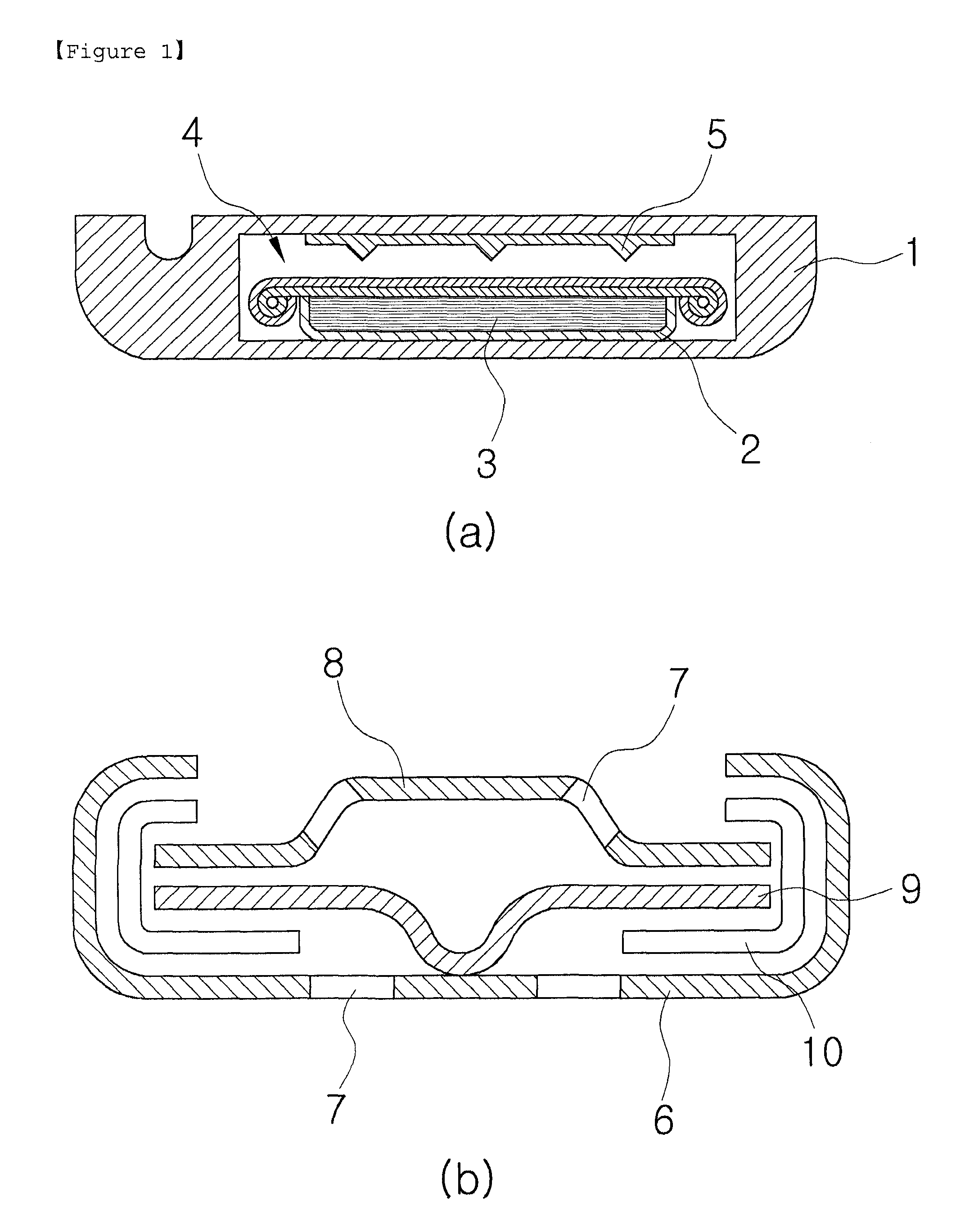
Since the prior technology of protecting the secondary battery 4 using the projecting portion 5 requires an additional production process, there are problems of decreasing productivity and not ensuring destruction reliability.
Further, there is a problem of contrary inconsistency that the stack portion must have sealing property and destruction property simultaneously.
There is a further problem in that a harmful gas is exhausted due to the explosion of the sealing unit caused by the internal pressure of the battery, which damages the electronic circuit and adversely affect the human body.
Since the case of a pouch-type secondary battery is formed of a flexible thin plate produced by mixing the metal material such as aluminum and resin material such as polymer resin, it is difficult to structure the safety apparatus according to the prior art.
The prior art using the rupture disc 9 has problems in that harmful gas is discharged when the disc is destroyed and operated and also the spark generated when the rupture disc 9 is destroyed serves as a fire source of the discharge gas, which results in fire and explosion.
Further, there is a technological limit to directly interrupt the battery circuit in a case of the secondary battery for use in vehicle in which high voltage and large amount of current are applied.

Method used


Image

  • Safety Apparatus and Protection Method of Secondary Battery for Electric Vehicle Using Switch
  • Safety Apparatus and Protection Method of Secondary Battery for Electric Vehicle Using Switch
  • Safety Apparatus and Protection Method of Secondary Battery for Electric Vehicle Using Switch

Examples


embodiment 1

[0063]A first embodiment is directed to a safety apparatus and a protection method of the secondary battery for use in electric vehicle using the adjacent switch 150-1.

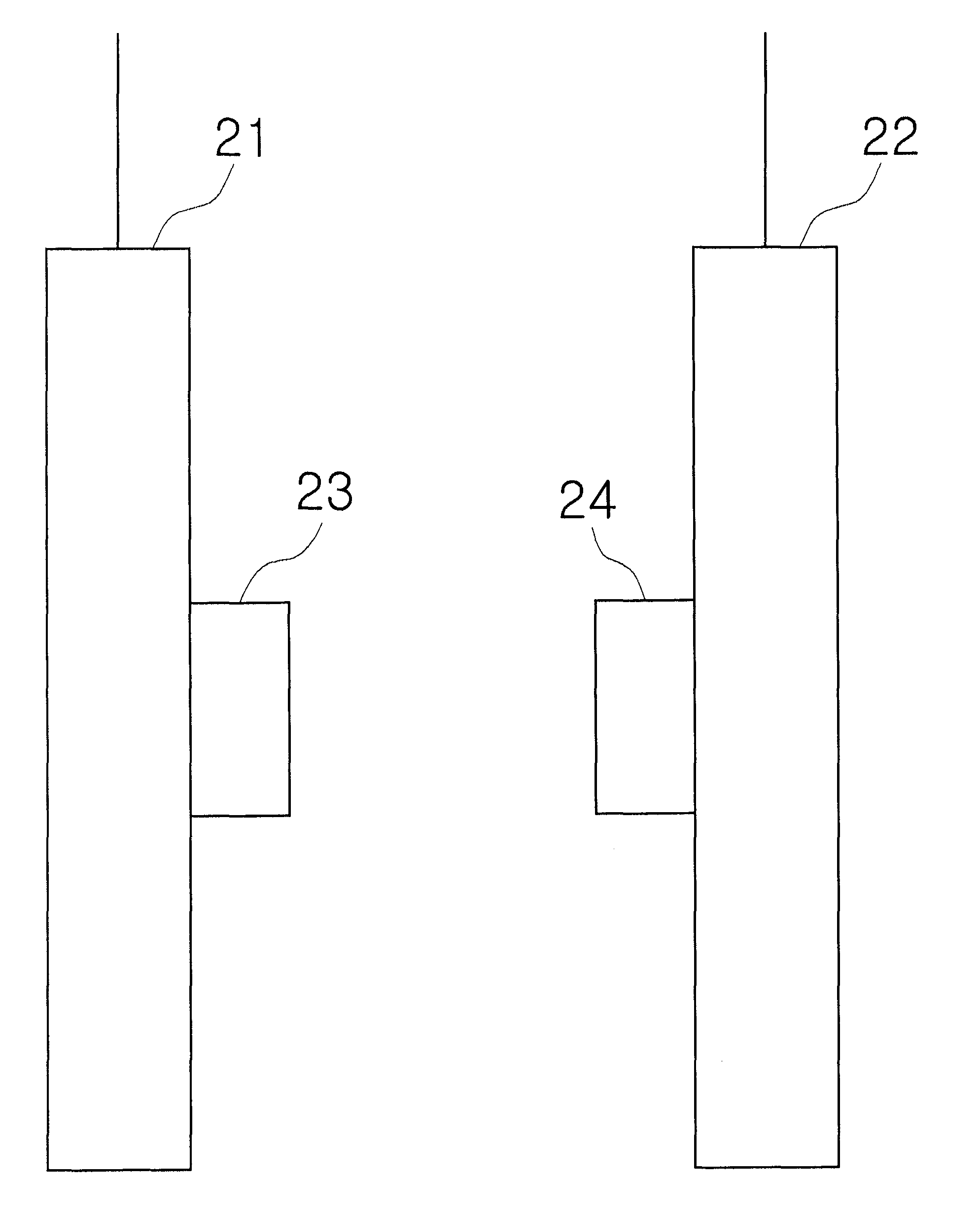
[0064]FIG. 4(a) is a conception view of the adjacent switch; FIG. 4(b) is a state view showing on-state of the adjacent switch according to the present invention; FIG. 4(c) is a state view showing off-state of the adjacent switch according to the present invention; and FIG. 8 is a battery control systematic view and a power systematic view of the electric vehicle drive motor, including a protection circuit to which the adjacent switch is applied according to the present invention.

[0065]As shown in FIG. 4(a), a first coupling body 31 and a second coupling body 32 are provided within a sealing case 35 of the adjacent switch 150-1.

[0066]At this time, the first coupling body 31 is connected to a first switch lead 33 and the second coupling body 32 is connected to a second switch lead 34. In addition, a magnet for controll...

second embodiment

[0080]A second embodiment is directed to a safety apparatus and a protection method of the secondary battery for use in electric vehicle using the micro switch 160-1.

[0081]FIG. 5(a) is a conception view showing a micro switch; FIG. 5(b) is a state view showing on-state of the micro switch according to the present invention; FIG. 5(c) is a state view showing off-state of the micro switch according to the present invention; and FIG. 9 is a battery control systematic view and a power systematic view of the electric vehicle drive motor, including a protection circuit to which the micro switch is applied according to the present invention.

[0082]As shown in FIG. 5(a), the micro switch 160-1 has a first stationary contact 41, a second contact 42 and a movable contact 43 provided within a housing 48.

[0083]At this time, a third switch lead 44 is connected to the movable contact 43 and a fourth lead 45 is connected to the first stationary contact 41.

[0084]Further, a press button 47 provided o...

third embodiment

[0098]A third embodiment is directed to a safety apparatus and a protection method of the secondary battery for use in electric vehicle using a rupture switch 90-1.

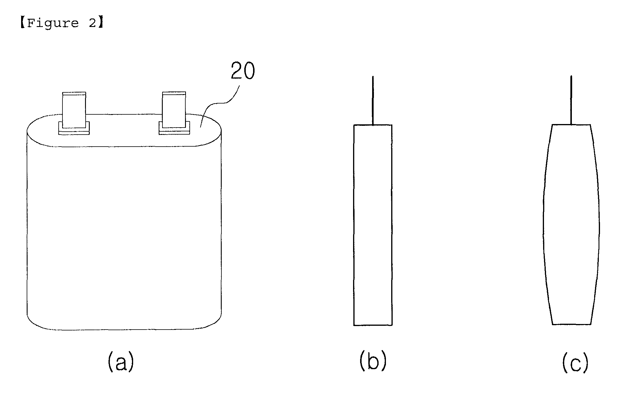
[0099]FIG. 6(a) is a conception view of a rupture switch according to the present invention, and FIG. 6(b) is a conception view of the rupture switch attached to the pouch-type lithium polymer secondary battery.

[0100]As shown in FIG. 6(a), the rupture switch 90-1 is consisted of a “U” type metal piece.

[0101]The rupture switch 90-1 is attached on one surface of the pouch-type lithium polymer secondary battery 20 using a first holding unit 50 provided on one side of the “U” type metal piece and a second holding unit 51 and a third holding unit 52 provided on both end of the other side of the “U” type metal piece.

[0102]The rupture switch 90-1 is held in the pouch-type lithium polymer secondary battery 20 using a first holding hole 50-1, a second holding hole 50-2, a third holding hole 51-1 and a fourth holding hole 52-1 prov...


PUM


Abstract

The present invention relates to a safety apparatus and a protection method of a secondary battery, which can prevent explosion and fire of the secondary battery using a switch or a rupture switch attached on the outside of the secondary battery if a swelling degree of the secondary battery reaches a predetermined value when the secondary battery is swelled due to abnormal usage such as overcharge, short-circuit, reverse-connection and heat-exposure of large-capacity lithium polymer battery.

Description

TECHNICAL FIELD[0001]The present invention relates to a safety apparatus of a secondary battery, and more particularly, to a safety apparatus of a secondary battery which can prevent explosion and fire of the secondary battery using a switch or a rupture switch attached on the outside of the secondary battery if a swelling degree of the secondary battery reaches a predetermined value when the secondary battery is swelled due to abnormal usage such as overcharge, short-circuit, reverse-connection and heat-exposure of large-capacity lithium polymer battery.BACKGROUND ART[0002]Typically, the secondary battery is capable of being recharged and being large-scaled. Cadmium nickel, hydrogen nickel and lithium ion battery can be taken as representative examples. Amongst them, the lithium ion battery is promising as next-generation power source because it has superior characteristics such as longevity and high capacity. However, if the lithium ion battery is exposed to abnormal usage environ...

Claims


Application Information

Patent Timeline
IPC IPC(8): H01M2/00H01M10/00H01M10/44H01H85/00H01M50/574
CPCH01M2/34Y02E60/12H01M10/052H01M10/4235Y02T10/7011B60L3/0046B60L3/0069B60L3/04B60L11/1803B60L11/1879B60L2250/10H01M10/0565H01M2200/20H01M2220/20Y02T10/7005Y02T10/705H01M2/345B60L50/51B60L50/64B60L58/15B60L58/10Y02E60/10Y02T10/70H01M50/578Y02P70/50H01M50/574H01H33/08H01H35/006H01H71/12B60Y2200/91H01M50/572
Inventor JANG, SOOYEUPOH, JEONKEUN
Owner SK ON CO LTD
Learn More