Ventilation apparatus for pulmonary scintigraphy

a ventilation apparatus and pulmonary scintigraphy technology, applied in the field of lung ventilatory scintigraphy, can solve the problems of not being able to avoid showing the marker, the patient is subject to a large quantity of dangerous marking particles, and the scintigraphy test cannot be carried out without affecting, so as to improve the quality of marked air

Inactive Publication Date: 2010-09-30
AZIENDA OSPEDALIERO UNIVRIA PISANA
View PDF10 Cites 48 Cited by
  • Summary
  • Abstract
  • Description
  • Claims
  • Application Information

AI Technical Summary

Benefits of technology

[0015]It is therefore object of the present invention to provide a ventilation apparatus for pulmonary scintigraphy that is able to select the size of particles of marked aerosol that reaches the patient and therefore to improve the quality of marked air that the patient breathes in.
[0016]It is another object of the present invention to provide a ventilation apparatus that provides a uniform distribution of the marked aerosol in the bronchial branches, i.e. without hyper accumulation of marker, reducing the impact on the bronchial branches and making easier a direct peripheral distribution of the marker.
[0018]It is also object of the present invention to provide a ventilation apparatus for pulmonary scintigraphy capable of reducing the time necessary for executing a scintigraphical test.
[0019]It is a further object of the present invention to provide a ventilation apparatus for pulmonary scintigraphy for carrying out at the same time a non invasive mechanical ventilation with nasal mask, without affecting the pressure cycles on which the apparatus works and without polluting the apparatus and the environment with exhaled marked aerosol.

Problems solved by technology

Notwithstanding the deferred images do not show said radioactive accumulation, however they cannot avoid showing the marker swallowed with the saliva through the oesophagus and the stomach, since scintigraphy detects it.
Another problem is that a scintigraphy test, during Non-Invasive Mechanical Ventilation with nasal mask, cannot be carried out without affecting the pressure control on which the apparatus is based and without polluting the apparatus and the environment with the exhaled marked aerosol.
This occurs especially if the marking particles are too large.If the breathed in air is too poor of marker, the patient has to breathe in and out the marked air for a long time.In both cases, the patient is subject to a quantity of dangerous marking particles more than necessary.
The most remote parts of the lungs that are the most important for the scintigraphy test and are those where not much marking particles deposit, causing the scintigraphic imaging to be worse in that parts.

Method used


Image

  • Ventilation apparatus for pulmonary scintigraphy
  • Ventilation apparatus for pulmonary scintigraphy
  • Ventilation apparatus for pulmonary scintigraphy

Examples


Embodiment Construction

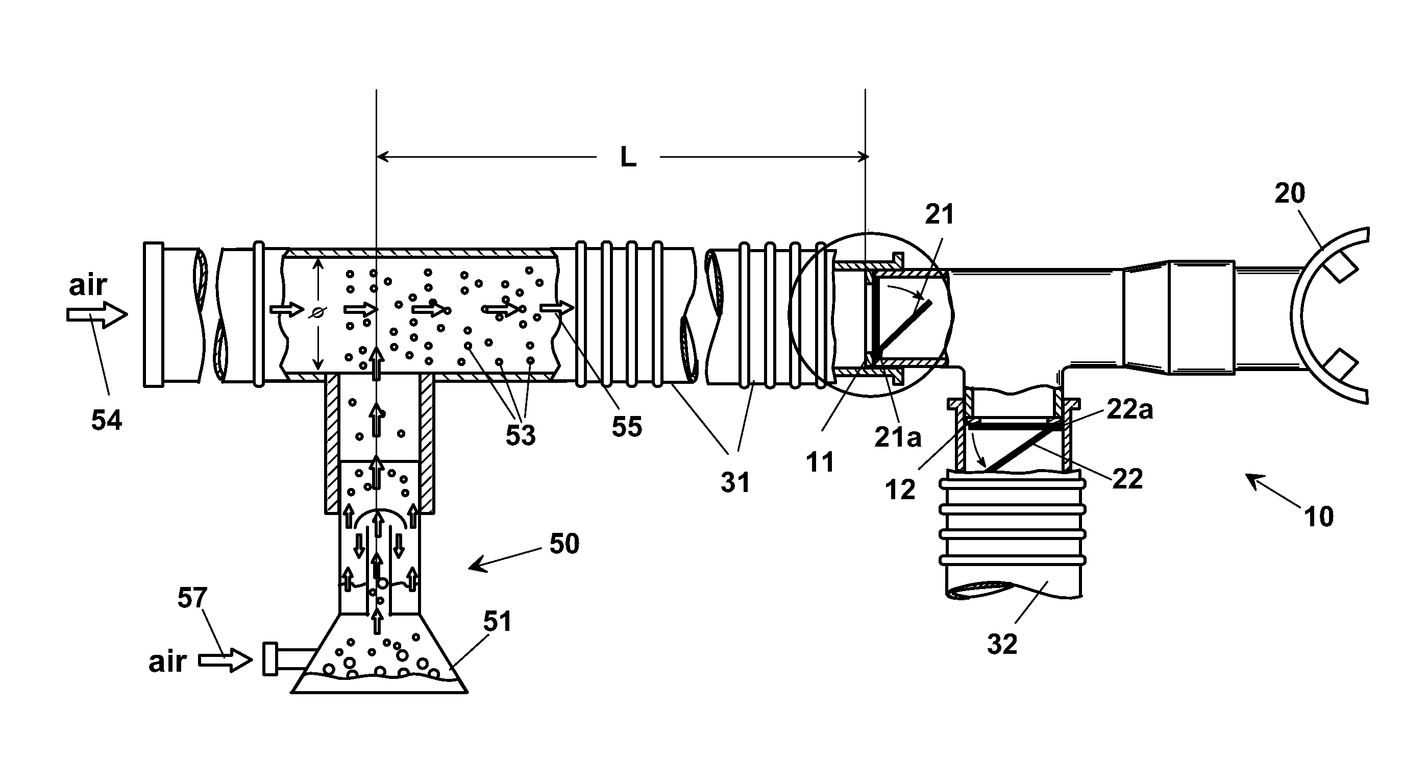
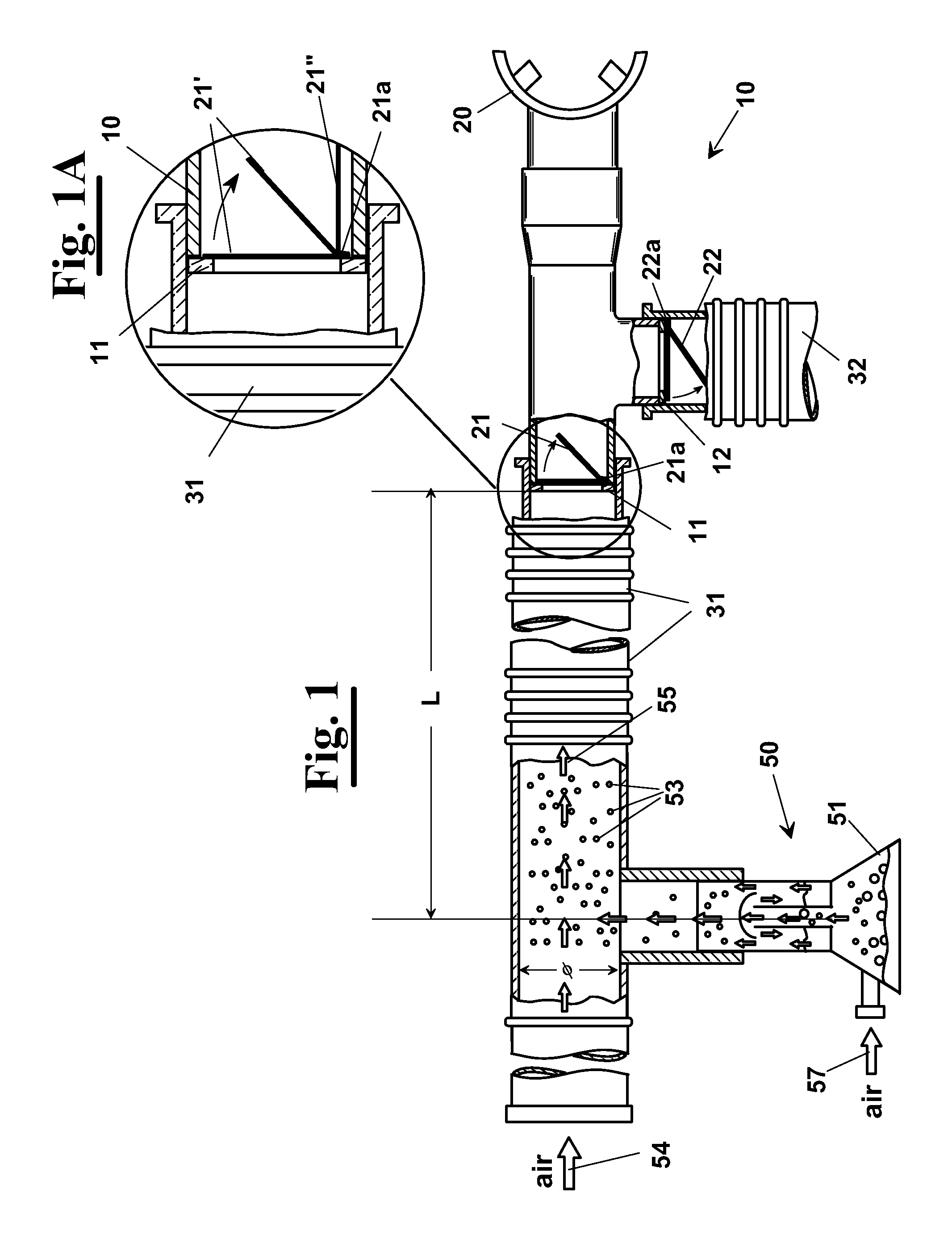
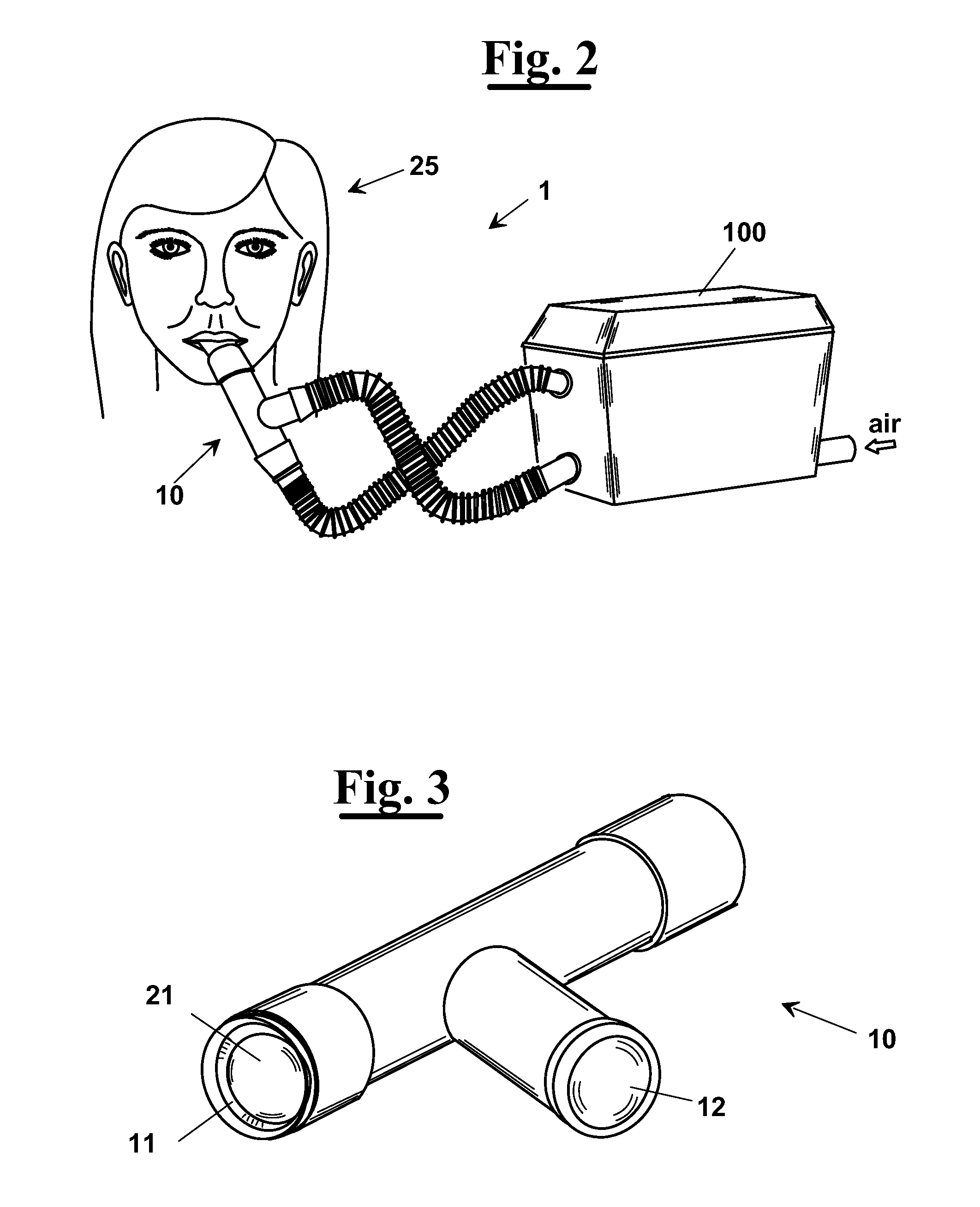
[0070]In FIG. 1 a first embodiment is shown of a ventilation apparatus 1 for pulmonary scintigraphy, according to the present invention.

[0071]It comprises an inhalation collector 10 to which an element of inhalation, for example a mouthpiece 20, a feed duct 31, defining a flow of marked aerosol 55, and an outlet duct 32 for disposal of exhaled flow 56 and any aerosol surplus, are connected. Normally the feeding air is of bi-level type, whereby the air flow rate when breathing out is low, even if always positive.

[0072]In particular, as shown in FIG. 1, the flow of marked aerosol 55 is obtained mixing upstream of collector a current of nano-colloidal particles 53, marked for example with Tc-99m and delivered by a nebulizer 50, with an air flow 54. In particular, nebulizer 50 is a Venturi jet nebulizer adapted to be fed by an air flow 57 set between 15-25 l / min and to generate a flow of marked aerosol 55 including marked aerosolized particles 53, i.e. marked droplets, sized between 0.0...


PUM


Abstract

A ventilation apparatus (1) for pulmonary scintigraphy, having an inhalation collector (10) to which an element of inhalation (20), a feed duct (31), defining a flow of marked aerosol (55), and an outlet duct (32), for disposal of exhaled flow and any aerosol surplus, are connected. The feeding air may be of bi-level type, whereby the air flow rate when breathing out is low, even if always positive. The collector (10) has a first interposition element (21) located at the connection with the air feeding tube (31) that only allows inlet flow towards the patient. A second interposition element (22) is located at the connection with outlet duct (32). The presence of one-way valve(s) (21, 22) allows breathing of the marked aerosol in the bronchial branches of the patient (20) in a completely natural manner following physiologic respiration and avoiding hyper-accumulation of marker in the largest bronchial branches. Scintigraphy is also allowed during non-invasive mechanical ventilation, carried out through the ventilation apparatus (1).

Description

[0001]This application is a continuation-in-part of Ser. No. 10 / 508,015, filed Sep. 29, 2004, which is a filing under 35 USC 371 of PCT / IB03 / 01156 filed Mar. 28, 2003.[0002]The present invention relates to the medical field and in particular it relates to a ventilation apparatus for pulmonary scintigraphy, capable to provide a uniform distribution of a marking substance in a patient's lungs.[0003]Furthermore, the invention relates to a method for inhalation of this substance.BACKGROUND OF THE INVENTION[0004]As known, Lungs Ventilatory Scintigraphy is a technique for detecting the distribution of lungs ventilation in patients with pathology of the respiratory system such as bronchial asthma, chronic bronchitis and emphysema. It consists in ventilating into the patient an inert gas such as 133Xe, 127Xe, the 81Kr, or aerosol, usually 99mTc-DTPA (diethylen-triamino-pentacetic acid) or sulphide colloidal 99mTc, for then looking at its distribution in the lungs.[0005]With the perfusion an...

Claims


Application Information

Patent Timeline
Patent Type & Authority Applications(United States)
IPC IPC(8): A61B6/02A61M11/00
CPCA61B5/0813A61M15/02A61M16/06A61B6/4258A61M16/208A61M16/0833A61M16/08
Inventor ALBERTELLI, ROBERTO
Owner AZIENDA OSPEDALIERO UNIVRIA PISANA
Why Eureka
Try Eureka