Variable height, multi-axial bone screw assembly

a multi-axial, bone screw technology, applied in the direction of ligaments, prostheses, osteosynthesis devices, etc., can solve the problems of undesirable looseness in the bone screw assembly, drawbacks and limitations, dangerous problems, etc., and achieve the effect of reliable securement of the collet bulb

Inactive Publication Date: 2010-09-30
SIMONSON PETER M
View PDF29 Cites 106 Cited by
  • Summary
  • Abstract
  • Description
  • Claims
  • Application Information

AI Technical Summary

Benefits of technology

[0008]The present invention provides a simple, variable height multi-axial bone screw assembly that allows bone screws to engage a fixed cylindrical rod in any degree of angular orientation or direction. In a preferred embodiment, the bone screw assembly of the present invention includes a bone screw, a collet, a tulip shaped connector, a crown member, a locking washer, a rod and a set-screw. In this embodiment, the bone screw has a threaded shank at its lower end and a generally cylindrical shaft at its upper end. The collet has a cylindrically shaped lower end and a generally bulb shaped upper end which is designed to be received by the tulip shaped connector. This collet also has an interior bore which allows the collet to slide over the bone screw shaft like a sleeve. By changing the amount of the bone screw shaft covered by the collet, one can vary the height of the bone screw vis-à-vis the tulip shaped connector.
[0009]The tulip shaped connector has a central bore that is designed, at its lower end, to receive the collet bulb. Within the tulip shaped connector, the locking washer can be placed below the collet bulb and the crown member can be placed above the collet bulb to r

Problems solved by technology

While the Sherman bone screw assembly has been used in many surgeries, it has drawbacks and limitations.
These gaps can create undesirable looseness in the bone screw assembly.
Moreover,

Method used


Image

  • Variable height, multi-axial bone screw assembly
  • Variable height, multi-axial bone screw assembly
  • Variable height, multi-axial bone screw assembly

Examples


Embodiment Construction

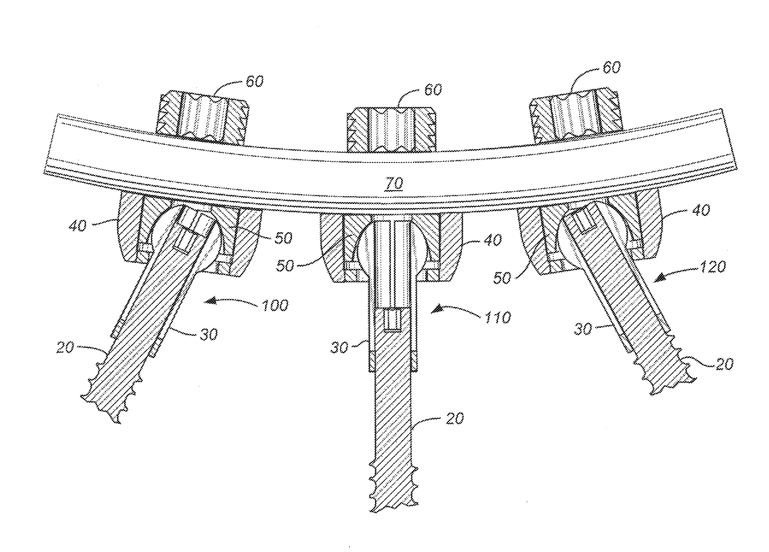
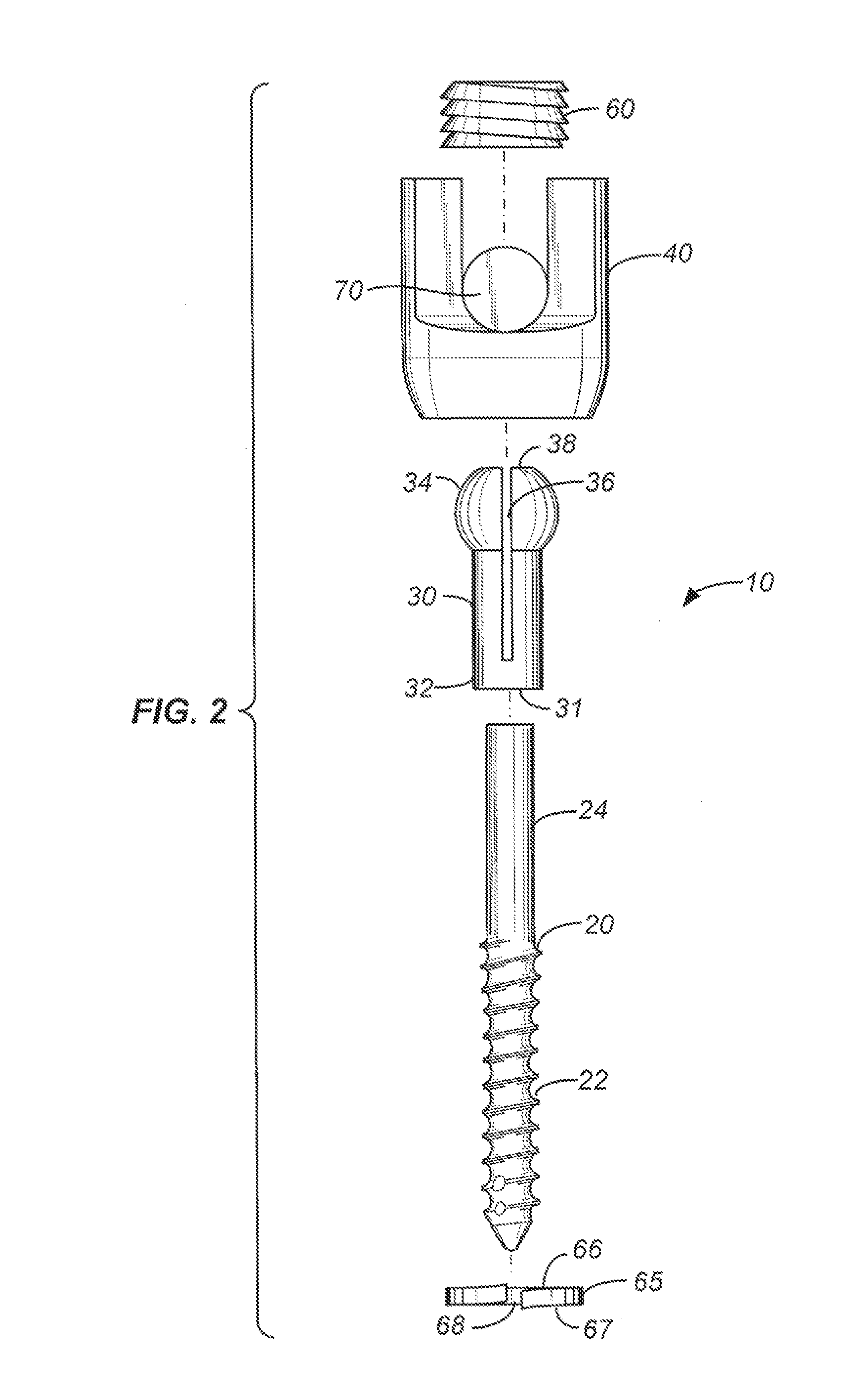
[0021]Referring now to FIG. 2, a preferred embodiment of the bone screw assembly 10 of the present invention is shown in exploded form. Components of this bone screw assembly 10 embodiment include a bone screw 20, a collet 30, a tulip shaped connector 40, a crown member 50 (see FIG. 3), an optional locking washer 65, a rod 70 and a set screw 60. The components of the bone screw assembly 10 can be metallic, such as titanium, titanium alloy or stainless steel, or non-metallic, such as PEEK or other types of plastics, or a combination thereof.

[0022]The bone screw 20 in this preferred embodiment has a threaded shank 22 at its lower end with threads configured to solidly anchor the bone screw within a bone. Preferably, the threads are cancellous threads, or threads readily adapted for solid fixation within the cancellous bone of the vertebral body. It is understood that the threaded shank 22 can have a variety of configurations depending upon the nature of the bone within which the bone ...


PUM


Abstract

A variable height, multi-axial bone screw assembly including a bone screw, a collet, a tulip shaped connector, a crown member, a rod and a set-screw. The bone screw has threads at its lower end and a generally cylindrical shaft at its upper end. The collet has a cylindrically shaped lower end to hold and grasp the bone screw shaft as well as a generally bulb shaped upper end to be received by the tulip shaped connector. By changing the position of the bone screw shaft grasped by the collet, the height of the bone screw vis-à-vis the tulip shaped connector can be varied. All the elements of the bone screw assembly are combined together by placing the collet head, crown member and rod within a central bore of the connector and firmly tightening them in place using the set screw.

Description

[0001]This application claims the benefit of U.S. Provisional Patent Application No. 61 / 163,313, filed Mar. 25, 2009, which application is incorporated herein by reference in its entirety.BACKGROUND OF THE INVENTION[0002]The present invention relates to a bone screw assembly for correcting misaligned spinal vertebrae. In particular, the present invention provides an assembly where the bone screws can not only be set at different axes vis-à-vis their connecting rods, but can also be set at different heights vis-à-vis such rods.[0003]Nerve compression and pain can be caused when vertebrae in the spine become misaligned. Spondylolisthesis, for example, is a condition where vertebrae become misaligned by slipping over one another either forwards (anterolisthesis) or backwards (retrolisthesis). Surgical techniques can be used to correct such misalignments. In one such surgical technique, bone screws are affixed to various vertebrae and, through suitable connectors, commonly attached to o...

Claims


Application Information

Patent Timeline
IPC IPC(8): A61B17/70A61B17/86B23P11/00
CPCA61B17/7037Y10T29/49826A61B17/8625
Inventor SIMONSON, PETER M.
Owner SIMONSON PETER M
Why Eureka
Try Eureka