Refrigeration apparatus

a technology of refrigerating apparatus and heat exchanger, which is applied in the direction of refrigeration machines, gas cycle refrigeration machines, corrosion prevention, etc., can solve the problems of difficult to achieve high operating efficiency, large heat radiation loss of heat exchangers, and temperature difference between refrigerants, so as to reduce the loss of defrosting capacity, reduce the loss of defrosting time, and minimize the loss of defrosting capacity

Active Publication Date: 2010-10-07
DAIKIN IND LTD
View PDF25 Cites 6 Cited by
  • Summary
  • Abstract
  • Description
  • Claims
  • Application Information

AI Technical Summary

Benefits of technology

[0009]However, when the only measure taken during the heating operation is to prevent the intercooler from functioning as a cooler using an intercooler bypass tube, the amount of frost deposits in the intercooler is small and defrosting of the intercooler will conclude sooner than in the heat source-side heat exchanger. Therefore, if refrigerant continues to flow to the intercooler even after defrosting of the intercooler is complete, heat is radiated from the intercooler to the exterior and the temperature of the refrigerant drawn into the second-stage compression element decreases, and as a result, the temperature of the refrigerant discharged from the compression mechanism decreases, creating a problem of the loss of defrosting capacity of the heat source-side heat exchanger.
[0010]In view of this, in this refrigeration apparatus, ...

Problems solved by technology

As a result, since the refrigerant discharged from the second-stage compression element of the compressor has a high temperature, there is a large difference in temperature between the refrigerant and the water or air as a cooling source in the outdoor heat exchanger functioning as a refrigerant cooler, and the outdoor heat exchanger has much heat radiation los...

Method used


Image

  • Refrigeration apparatus
  • Refrigeration apparatus
  • Refrigeration apparatus

Examples


modification 1

(3) Modification 1

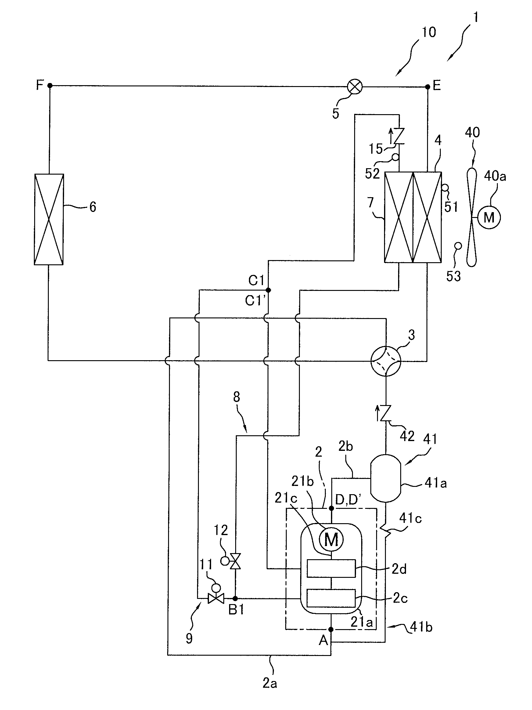
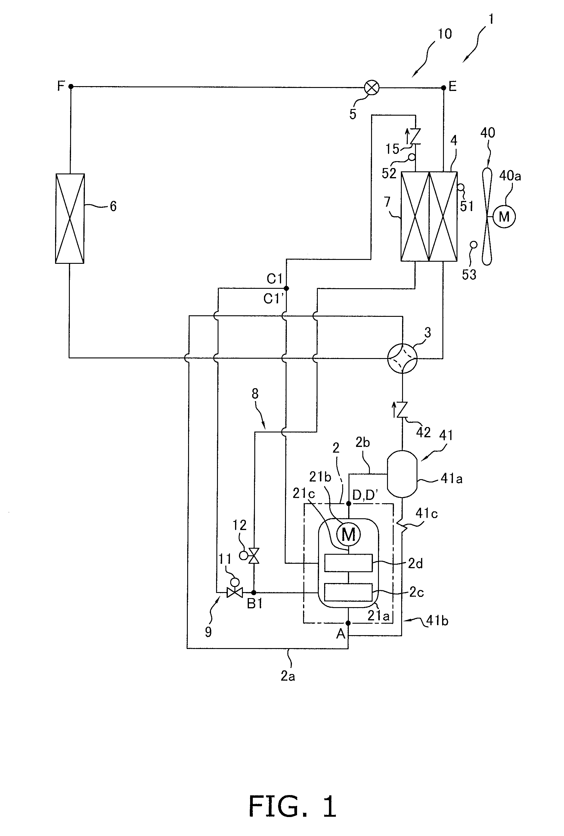
[0078]In the embodiment described above, in the air-conditioning apparatus 1 configured to be capable of being switched between the air-cooling operation and the air-warming operation by the switching mechanism 3, the air-cooling intercooler 7 integrated with the heat source-side heat exchanger 4 and the intercooler bypass tube 9 were provided. Using the intercooler 7 and the intercooler bypass tube 9, the intercooler 7 was made to function as a cooler when the switching mechanism 3 was set to a cooling operation state and the intercooler 7 was made to not function as a cooler when the switching mechanism 3 was set to a heating operation state, thereby reducing the heat radiation loss in the heat source-side heat exchanger 4 functioning as a refrigerant cooler and improving operating efficiency during the air-cooling operation, and minimizing heat radiation to the exterior to minimize the loss of heating performance during the air-warming operation. In addition to ...

modification 2

(4) Modification 2

[0117]In the defrosting operation in Modification 1 described above, although only temporarily until defrosting of the intercooler 7 is complete, the refrigerant flowing through the intercooler 7 condenses and the refrigerant drawn into the compression element 2d becomes wet, presenting a risk that wet compression will occur in the second-stage compression element 2d and the compression mechanism 2 will be overloaded.

[0118]In view of this, in the present modification, as shown in FIG. 16, in cases in which it is detected in step S7 that the refrigerant has condensed in the refrigerant flowing through the intercooler 7, intake wet prevention control is performed in step S8 for reducing the flow rate of refrigerant returned to the second-stage compression element 2d via the second-stage injection tube 19.

[0119]The decision of whether or not the refrigerant has condensed in the refrigerant flowing through the intercooler 7 in step S7 is based on the degree of superhea...

modification 3

(5) Modification 3

[0122]In the defrosting operation in Modifications 1 and 2 described above, after it has been detected that defrosting of the intercooler 7 is complete, the operation is performed to ensure that the intercooler 7 does not function as a cooler by closing the cooler on / off valve 12 and opening the intercooler bypass on / off valve 11 while the heat source-side heat exchanger 4 continues to be defrosted by the reverse cycle defrosting operation, heat radiation from the intercooler 7 to the exterior is prevented, and the decrease in defrosting capacity of the heat source-side heat exchanger 4 can be minimized.

[0123]However, when refrigerant does not flow to the intercooler 7, the temperature of the refrigerant drawn into the second-stage compression element 2d suddenly increases; therefore, there is a tendency for the refrigerant drawn into the second-stage compression element 2d to become less dense and for the flow rate of refrigerant drawn into the second-stage compre...


PUM


Abstract

A refrigeration apparatus uses a refrigerant that operates in a supercritical range. The refrigeration apparatus includes a compression mechanism, a heat source-side heat exchanger, an expansion mechanism, a usage-side heat exchanger, a switching mechanism, an intercooler which functions as a cooler of refrigerant discharged from a first-stage compression element of the compression mechanism and drawn into a second-stage compression element of the compression mechanism, and an intercooler bypass tube. The switching mechanism is configured to switch between cooling and heating operation states in which refrigerant is circulated differently. When a defrosting operation for defrosting the heat source-side heat exchanger is performed, refrigerant flows to the heat source-side heat exchanger and the intercooler. After defrosting of the intercooler is detected as being complete, the intercooler bypass tube is used to ensure that the refrigerant does not flow to the intercooler.

Description

TECHNICAL FIELD[0001]The present invention relates to a refrigeration apparatus, and particularly relates to a refrigeration apparatus which has a refrigerant circuit configured to be capable of switching between a cooling operation and a heating operation and which performs a multistage compression refrigeration cycle by using a refrigerant that operates in a supercritical range.BACKGROUND ART[0002]As one conventional example of a refrigeration apparatus which has a refrigerant circuit configured to be capable of switching between a cooling operation and a heating operation and which performs a multistage compression refrigeration cycle by using a refrigerant that operates in a supercritical range, Patent Document 1 discloses an air-conditioning apparatus which has a refrigerant circuit configured to be capable of switching between an air-cooling operation and an air-warming operation and which performs a two-stage compression refrigeration cycle by using carbon dioxide as a refrig...

Claims


Application Information

Patent Timeline
IPC IPC(8): F25B13/00
CPCF25B1/10F25B9/008F25B13/00F25B47/022F25B2309/061F25B2400/23F25B2400/04F25B2400/072F25B2400/075F25B2400/13F25B2313/02741
Inventor YOSHIMI, ATSUSHIFUJIMOTO, SHUJI
Owner DAIKIN IND LTD
Why Eureka
Try Eureka