Ultrasonic Measurement Method, Ultrasonic Measurement Apparatus, and Ultrasonic Sensor

a measurement method and ultrasonic technology, applied in the direction of instruments, specific gravity measurement, magnetic property measurement, etc., can solve the problems of noise in a similar manner, the three-dimensional focus of the ultrasonic wave on the point cannot be disadvantageously obtained, and the reflected high-frequency grating lobe from the bottom surface, etc., to achieve short inspection time, reduce noise, and high sn ratio

Active Publication Date: 2010-10-07
HITACHI-GE NUCLEAR ENERGY LTD
View PDF9 Cites 23 Cited by
  • Summary
  • Abstract
  • Description
  • Claims
  • Application Information

AI Technical Summary

Benefits of technology

[0075]According to the invention, it is possible to perform an inspection for a short time with a high SN ratio and a small variation (that depends on an inspection direction) in sensitivity by transmitting and receiving an ultrasonic wave to and from a region (that is to be measured) in a process for detecting a defect in all directions at 360 degrees using a matrix array sensor without performing mechan

Problems solved by technology

In the method described in JP-5-244691-A, however, since an ultrasonic wave spreads in a direction perpendicular to a scanning direction in a similar manner to an ultrasonic wave transmitted by a linear array sensor, an effect (that is specific to a matrix array sensor and is hereinafter referred to as a point focusin

Method used


Image

  • Ultrasonic Measurement Method, Ultrasonic Measurement Apparatus, and Ultrasonic Sensor
  • Ultrasonic Measurement Method, Ultrasonic Measurement Apparatus, and Ultrasonic Sensor
  • Ultrasonic Measurement Method, Ultrasonic Measurement Apparatus, and Ultrasonic Sensor

Examples


first embodiment

[0110]The configuration and operations of an ultrasonic measurement apparatus according to the present invention are described with reference to FIGS. 1 to 17.

[0111]First, the entire configuration of the ultrasonic measurement apparatus according to the present embodiment is described with reference to FIG. 1.

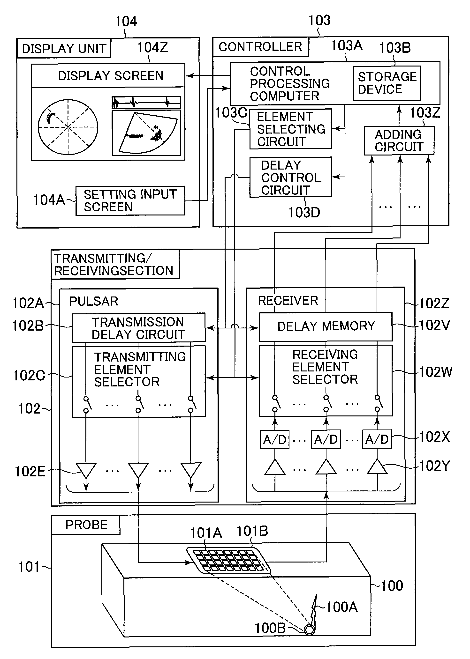
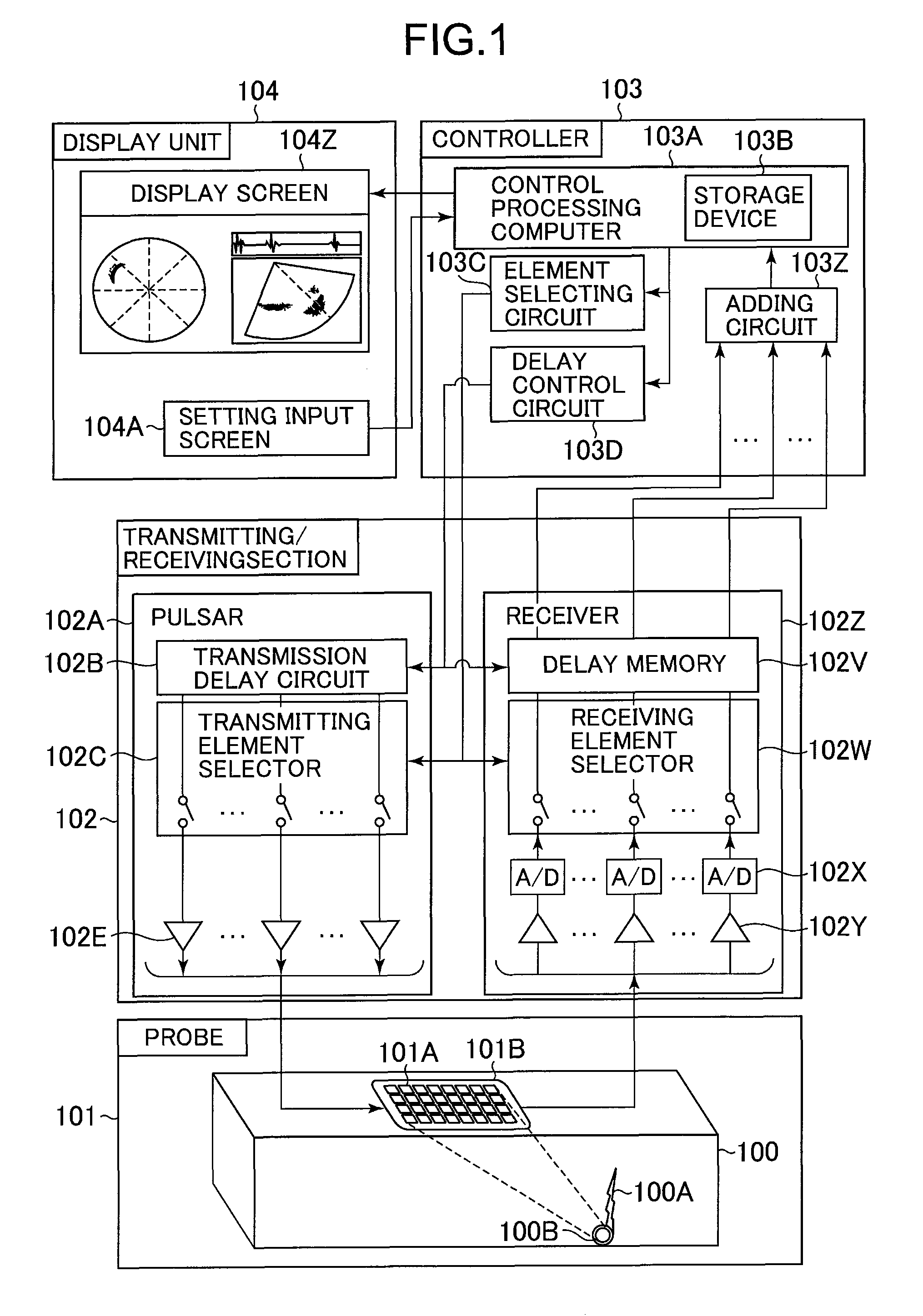
[0112]FIG. 1 is a block diagram showing the entire configuration of the ultrasonic measurement apparatus according to the present embodiment.

[0113]The ultrasonic measurement apparatus according to the present embodiment measures an object 100 and a reflection source 100A located inside the object or located on the surface of the object with an excellent SN ratio. The ultrasonic measurement apparatus according to the present embodiment has a probe 101, a transmitting / receiving section 102, a controller 103, and a display unit 104.

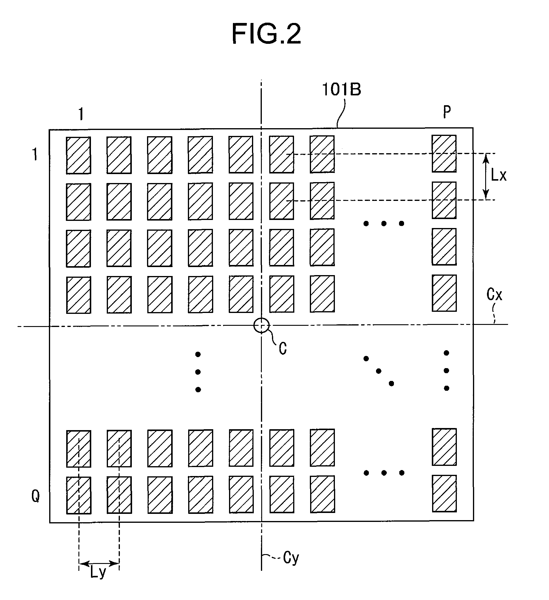
[0114]The probe 101 includes an array sensor 101B that transmits and receives an ultrasonic wave to the object 100 that is to be measured. The array se...

second embodiment

[0215]Next, the configuration and operations of an ultrasonic measurement apparatus according to the present invention are described with reference to FIGS. 18 to 20.

[0216]First, the entire configuration of the ultrasonic measurement apparatus according to the second embodiment is described with reference to FIG. 18.

[0217]FIG. 18 is a block diagram showing the entire configuration of the ultrasonic measurement apparatus according to the second embodiment of the present invention.

[0218]When such an array sensor as shown in FIG. 17 is used, the sizes of the elements that constitute the array sensor vary. Thus, the intensities of ultrasonic waves transmitted by the elements vary, and receiving sensitivity of the elements varies. To avoid this, an ultrasonic wave to be received is weighted by the apparatus (shown in FIG. 18) according to the present embodiment so that the intensity of the ultrasonic wave to be transmitted by each element or receiving sensitivity of each element is calib...

third embodiment

[0235]Next, the configuration and operations of an ultrasonic measurement apparatus according to the present invention are described with reference to FIGS. 21 and 22. The entire configuration of the ultrasonic measurement apparatus according to the present embodiment is the same as the configuration shown in FIG. 1 or 18. When the elements that are used for transmission and reception are set as shown in FIG. 13, 14, 15 or 16, the ultrasonic measurement apparatus shown in FIG. 1 can be used. When the elements that are used for transmission and reception are set as shown in FIG. 17, the ultrasonic measurement apparatus shown in FIG. 18 can be used.

[0236]FIG. 21 is a flowchart of a method for selecting a transmitting element and a receiving element from among the elements included in the ultrasonic measurement apparatus according to the present embodiment. FIG. 22 is a diagram showing the selected transmitting and receiving elements that are included in the ultrasonic measurement appa...


PUM


Abstract

An ultrasonic measurement method and an ultrasonic measurement apparatus are capable of performing an inspection for a short time with a high SN ratio and a small variation (that depends on an inspection direction) in sensitivity in a process for detecting a defect in all directions at 360 degrees using a matrix array sensor without performing mechanical scanning in all directions, while reducing noise that is caused by a bottom surface echo. An element selecting circuit selects a group of a plurality of ultrasonic transducer elements for transmission from among ultrasonic transducer elements that constitute a two-dimensional array sensor so that the ultrasonic transducer elements for selected for transmission are arranged in line symmetry with respect to a first line symmetric axis to set the group selected for transmission. The element selecting circuit selects a group of a plurality of ultrasonic transducer elements for reception so that the ultrasonic transducer elements selected for reception are arranged in line symmetry with respect to a second line symmetric axis that is perpendicular to the first line symmetric axis to set the group selected for reception. A transmitting element selector selects, as transmitting elements, the ultrasonic transducer elements set by the element selecting circuit. A receiving element selector selects, as receiving elements, the ultrasonic transducer elements set by the element selecting circuit.

Description

BACKGROUND OF THE INVENTION[0001]1. Field of the Invention[0002]The present invention relates to an ultrasonic measurement method and an ultrasonic measurement apparatus. The invention more particularly relates to an ultrasonic measurement method and an ultrasonic measurement apparatus, which are suitable to use phased array transducer (array sensor) having ultrasonic transducer elements that are two-dimensionally arranged, and to the ultrasonic sensor.[0003]2. Description of the Related Art[0004]In a conventional technique, when it is difficult to predict a direction in which a defect will become larger, the defect may be overlooked in an ultrasonic inspection process for transmitting an ultrasonic wave in an axial direction and a circumferential direction. Thus, there is demand for an ultrasonic inspection process for transmitting an ultrasonic wave in all directions. Since this type of defect is detected by an angle beam inspection process, an ultrasonic inspection technique that...

Claims


Application Information

Patent Timeline
IPC IPC(8): G01N29/04
CPCG01N29/262G10K11/345G01N2291/106G01N2291/0289
Inventor MIZOTA, HIROHISAKONO, NAOYUKIBABA, ATSUSHI
Owner HITACHI-GE NUCLEAR ENERGY LTD
Why Eureka
Try Eureka