Method and device for pseudo-differential transmission

a transmission method and transmission method technology, applied in the direction of waveguide type devices, orthogonal pcbs mounting, digital transmission, etc., can solve the problems of scheme being vulnerable to external crosstalk, method subject to two detrimental phenomena, and noise generation

Inactive Publication Date: 2010-10-07
ZXNOISE LLC
View PDF17 Cites 9 Cited by
  • Summary
  • Abstract
  • Description
  • Claims
  • Application Information

AI Technical Summary

Problems solved by technology

This method is subject to two detrimental phenomena: echo and crosstalk.
However, there are other crosstalk phenomena which may produce noise.
This scheme is consequently vulnerable to external crosstalk (it is also subject to internal crosstalk).
Consequently, in the case of FIG. 2, substantial reflections of signals occur, and the specialists know that this implies limitations on the length L of the interconnection (L must be sufficiently small) and on the available bandwidth.
This implies that it is a priori not possible to model propagation in the interconnection using a multiconductor transmission line having n+2=6 conductors, the multiconductor transmission line having uniform electrical characteristics over its length.
The currents flowing into the reference conductor (7) because of a loop A will consequently induce different voltages in the different conductors of the interconnection, and it will not be possible to eliminate the external crosstalk.
Consequently, there is no known method for transmission through an interconnection having n+1 conductors, effectively protected against external crosstalk and capable of operating with reduced reflections.
However, prior art does not describe the conditions, relating to the structure of the interconnection and to proportioning of such terminations, which provide an effective reduction of reflections and external crosstalk.
Consequently, there is no known method for transmission through an interconnection having n+1 conductors, effectively protected against external crosstalk and capable of operating with reduced reflections.

Method used


Image

  • Method and device for pseudo-differential transmission
  • Method and device for pseudo-differential transmission
  • Method and device for pseudo-differential transmission

Examples


first embodiment

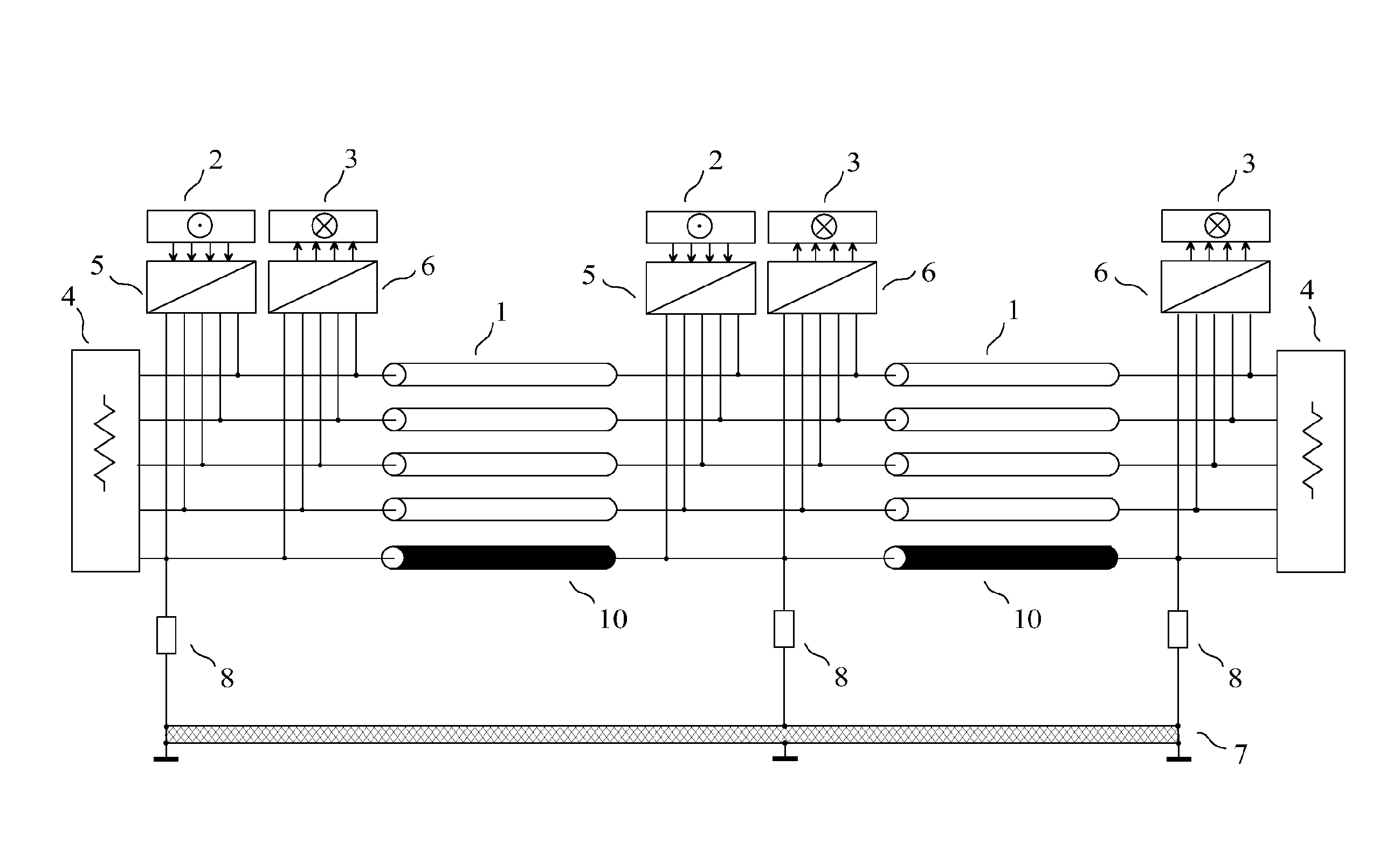
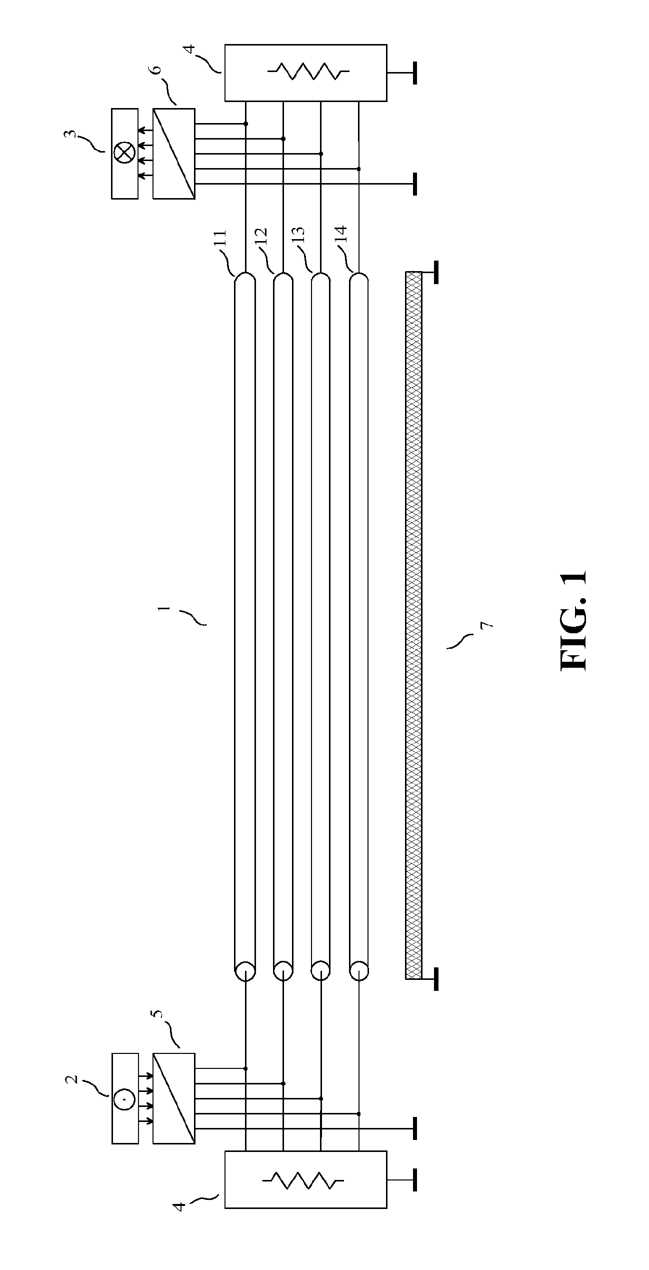
[0125]As a first embodiment of a device for implementing the method of the invention, given by way of non-limiting example, we have represented in FIG. 7 a device of the invention comprising an interconnection (1) having n=4 transmission conductors (11) (12) (13) (14) and a return conductor (10) distinct from the reference conductor (7). The two termination circuits (4) are connected to the conductors (10) (11) (12) (13) (14) of the interconnection (1), the impedance matrix of each termination circuit with respect to the return conductor being approximately equal, in a part of a known frequency band used for transmission, to a diagonal matrix of size n×n minimizing a matrix norm of the matrix of the voltage reflection coefficients of the termination circuit with respect to the return conductor. The transmitting circuit (5) receives at its input the signals of the 4 channels of the source (2), and its n+1=5 output terminals are connected to the conductors (10) (11) (12) (13) (14) of ...

second embodiment

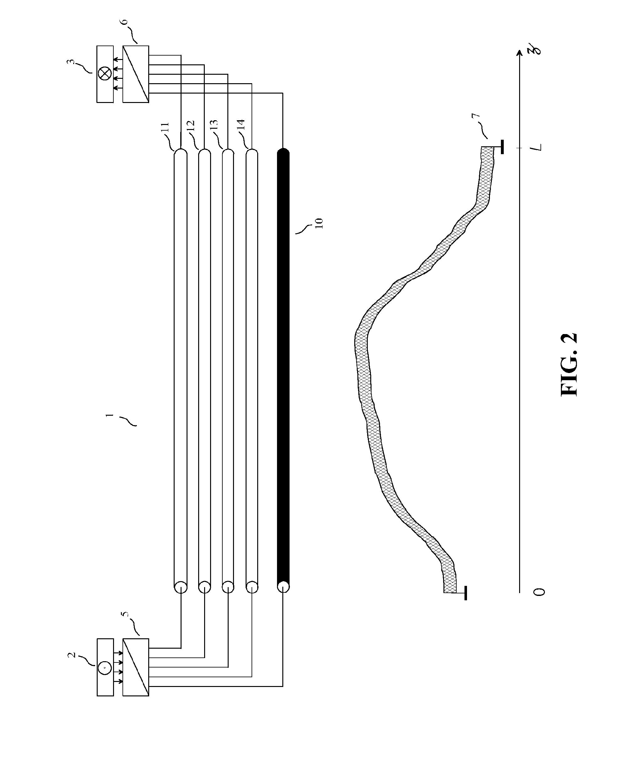
[0147]The second embodiment of a device for implementing the method of the invention, given by way of non-limiting example, also corresponds to the device of the invention shown in FIG. 7, and the explanations relating to FIG. 7 given in the presentation of the first embodiment are applicable to this second embodiment, except that, in this second embodiment, the transmitting circuit (5) is a “Pseudo-differential interfacing device having a balancing circuit” according to said French patent application Ser. No. 07 / 04889 and international application number PCT / IB2008 / 051942, which produces natural voltages referenced to the return conductor at its output (the transmission variables are therefore natural voltages referenced to the return conductor), each of these natural voltages referenced to the return conductor being mainly determined by the signal of only one channel of the source (2). The FIG. 8 is not applicable to this second embodiment.

[0148]The interconnection (1) is built in...

third embodiment

Best Mode

[0160]As a third embodiment of a device for implementing the method of the invention, given by way of non-limiting example and best mode of carrying out the invention, we have represented in FIG. 10 a device of the invention comprising an interconnection (1) having n=3 transmission conductors (11) (12) (13) and a return conductor (10) distinct from the reference conductor (7). A termination circuit (4) is connected to the conductors of the interconnection (1), the impedance matrix of the termination circuit with respect to the return conductor being, in a part of the frequency band used for transmission, approximately equal to a diagonal matrix of size n×n such that all components of the matrix of the voltage reflection coefficients of the termination circuit with respect to the return conductor have an absolute value less than or equal to 1 / 10. The transmitting circuit (5) receives at its input the signals of the 3 channels of the source (2), and its 4 output terminals are...


PUM


Abstract

The invention relates to a method and a device for pseudo-differential transmission in interconnections used for sending a plurality of electrical signals. The ends of an interconnection having 4 transmission conductors and a return conductor distinct from the reference conductor are each connected to a termination circuit. Three damping circuits are connected between the return conductor and the reference conductor. The transmitting circuits receive at their inputs the signals from the 4 channels of the two sources, and are connected to the conductors of the interconnection. The receiving circuits are connected to the conductors of the interconnection, each receiving circuit being such that the 4 channels of a source connected to a transmitting circuit in the activated state are sent to the four channels of the destinations without noticeable external crosstalk.

Description

FIELD OF THE INVENTION[0001]The invention relates to a method and a device for pseudo-differential transmission through interconnections used for sending a plurality of electrical signals, such as the interconnections made with multiconductor cables, or with the traces of a printed circuit board, or inside an integrated circuit.[0002]The French patent application Ser. No. 07 / 05260 of 20 Jul. 2007, entitled “Procédé et dispositif pour les transmissions pseudo-différentielles” is incorporated by reference.PRIOR ART[0003]Let us consider the problem of transmission through an interconnection, for obtaining m transmission channels, m being an integer greater than or equal to 2. Each transmission channel may be used for transmitting signals of any type, for instance analog signals or digital signals, from a source to a destination. We consider here that a digital signal is a signal whose value is defined only at discrete points in time, the set of the values that the signal may take on be...

Claims


Application Information

Patent Timeline
Patent Type & Authority Applications(United States)
IPC IPC(8): H03H9/00
CPCH04L25/0272H04L25/0298H05K2201/09236H05K2201/044H05K1/0216
Inventor BROYDE, FREDERICCLAVELIER, EVELYNE
Owner ZXNOISE LLC
Why Eureka
Try Eureka