

Signal processing device, signal processing method, and computer program
a signal processing and signal processing technology, applied in the field of signal processing devices, signal processing methods, computer programs, can solve the problem of extremely high cost of such circuits, and achieve the effect of reproducing sound more faithful to original sound
- Summary
- Abstract
- Description
- Claims
- Application Information
AI Technical Summary
Benefits of technology
Problems solved by technology
Method used
Image

Examples
first embodiment
1. First Embodiment
[A Configuration Example of a Sound Recording Device According to a First Embodiment
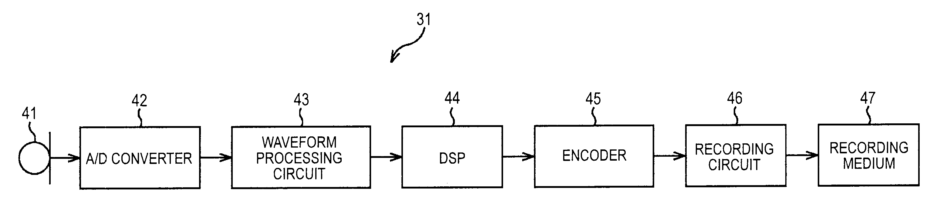
[0067]FIG. 5 is a block diagram of a configuration example of a sound recording device as a signal processing device according to a first embodiment of the present invention.
[0068]A sound recording device 31 of the example shown in FIG. 5 is configured as, for example, a sound recording section of a video camera. The sound recording device 31 receives the input of sound on the outside as a sound signal via a microphone 41 and applies predetermined processing to the sound. The sound recording device 31 records a sound signal obtained as a result of the processing in a recording medium, for example, a recording medium 47 inserted in the sound recording device 31.
[0069]The sound recording device 31 includes the microphone 41, an A / D converter 42, a waveform processing circuit 43, a DSP (Digital Signal Processor) 44, an encoder 45, and a recording circuit 46.
[0070]The microphone 41 co...
second embodiment
[0204]A second embodiment of the present invention is explained below.
[A Configuration Example of a Sound Reproducing Device According to the Second Embodiment]
[0205]FIG. 21 is a block diagram of a configuration example of a sound reproducing device as a signal processing device according to the second embodiment.
[0206]A sound reproducing device 141 of the example shown in FIG. 21 is configured as, for example, a sound reproduction section of a video camera. The sound reproducing device 141 reads out a sound signal from a recording medium, for example, a recording medium 151 inserted therein, reproduces the sound signal, and applies predetermined processing to the sound signal. The sound reproducing device 141 outputs a sound signal obtained as a result of the processing to the outside as sound via a speaker 156.
[0207]The sound reproducing device 141 of the example shown in FIG. 21 uses a waveform processing circuit same as the waveform processing circuit 43 in the sound recording d...
third embodiment
[0211]A third embodiment of the present invention is explained below.
[A Configuration Example of a Sound Recording Device According to the Third Embodiment]
[0212]FIG. 22 is a block diagram of a configuration example of a sound recording device as a signal processing device according to the third embodiment.
[0213]A sound recording device 201 of the example shown in FIG. 22 includes a waveform processing circuit 211 of the example shown in FIG. 22 instead of the waveform processing circuit 43 of the sound recording device 31 of the example shown in FIG. 13. The waveform processing circuit 211 of the example shown in FIG. 22 includes a determining circuit 221 instead of the determining circuit 104 of the sound recording device 31 of the example shown in FIG. 13. In the determining circuit 221 of the example shown in FIG. 22, the switch 112, the switch 116, the amplitude compressing circuit 119, and the switch 120 of the example shown in FIG. 13 are deleted. A switch 231, an amplitude c...
PUM
 Abstract
Description
Claims
Application Information