Image processing apparatus and c0mputer program

Active Publication Date: 2010-10-07
KDDI CORP
View PDF3 Cites 95 Cited by
  • Summary
  • Abstract
  • Description
  • Claims
  • Application Information

AI Technical Summary

Benefits of technology

[0014]The difference between the projected depth map and the depth map of the second

Problems solved by technology

However, it is

Method used


Image

  • Image processing apparatus and c0mputer program
  • Image processing apparatus and c0mputer program
  • Image processing apparatus and c0mputer program

Examples


Embodiment Construction

[0027]A viewpoint is specified by a position and a direction, and “an image of a viewpoint” or “an image from a viewpoint” means an image within the predetermined visual field at the position and the direction specified by the viewpoint in the following description. Further, camera parameters of a camera can be considered as a viewpoint and a visual field, and an image captured by a camera is also referred to as an image of a viewpoint. In this case, a position of the viewpoint is a position of the camera, and a direction of the viewpoint is a direction of the camera.

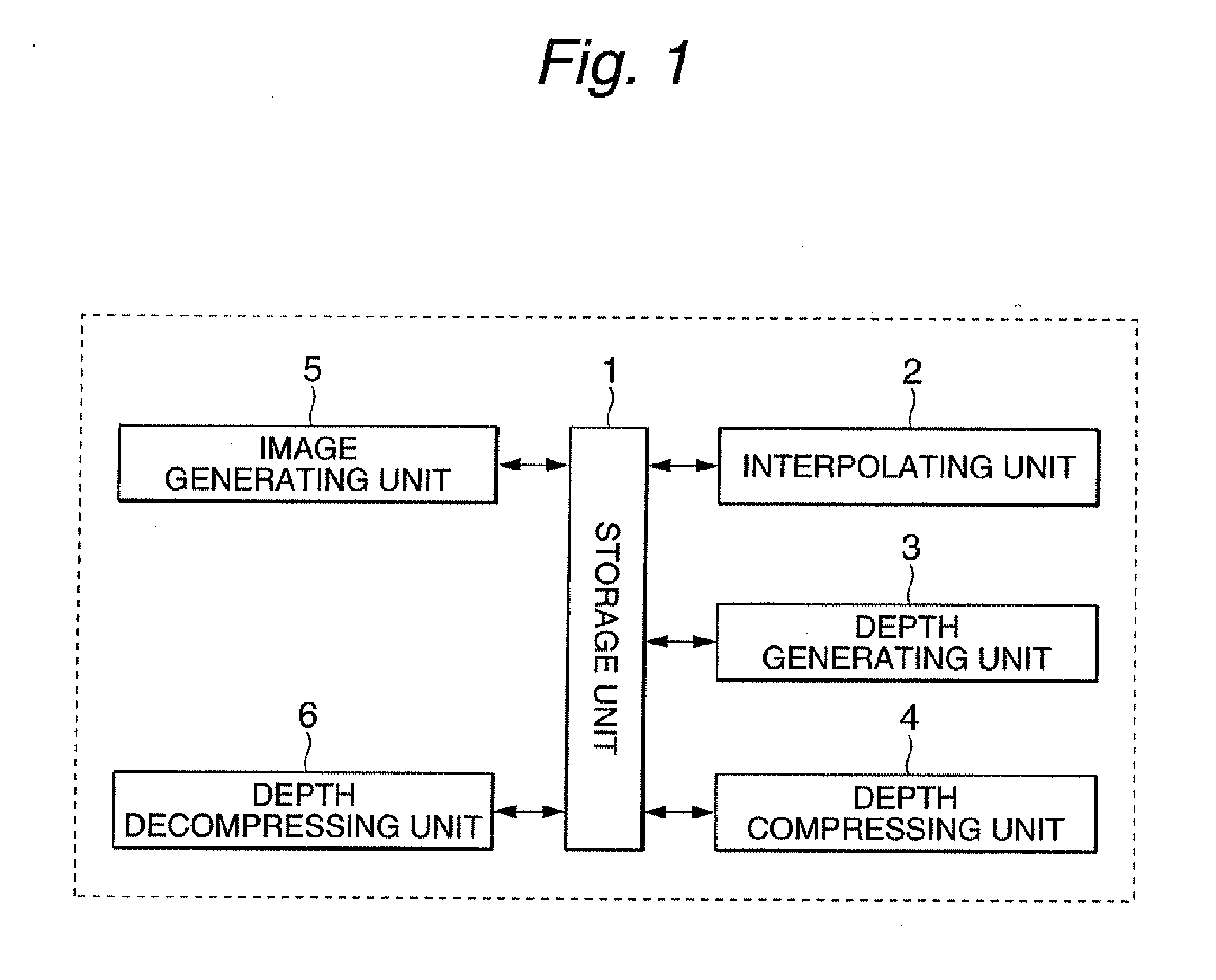
[0028]FIG. 1 shows a block diagram of an image processing apparatus according to the invention. As shown in FIG. 1, the image processing apparatus has a storage unit 1, an interpolating unit 2, a depth generating unit 3, a depth compressing unit 4, an image generating unit 5 and a depth decompressing unit 6.

[0029]The interpolating unit 2 generates a plurality of new images of predetermined viewpoints from images in moti...


PUM


Abstract

The present invention relates to an image processing apparatus for compressing image data used in an image generating apparatus for generating a free-viewpoint image. According to the invention, the apparatus has a selecting unit that selects one image as a first image, and defines other images as second images, a projective transformation unit that generates a projected depth map of a second image from a depth map of the first image, a subtracting unit that creates a difference map of the second image, and a storage unit that stores the depth map of the first image and the difference map of the second image. Here, the difference map is a difference between a depth map of the second image and the projected depth map of the second image, and the depth map indicates a depth value of each pixel of a corresponding image.

Description

PRIORITY CLAIM[0001]This application claims priority from Japanese patent application No. 2009-90659 filed on Apr. 3, 2009, which is incorporated herein by reference.BACKGROUND OF THE INVENTION[0002]1. Field of the Invention[0003]The present invention relates to a free viewpoint video system.[0004]2. Description of the Related Art[0005]Various proposals has been made for generating a free viewpoint video from motion pictures captured by several cameras, for example, in Japanese patent publication 2008-15756A1, “Ray-Based Creation of Photo-Realistic Virtual World” by Takeshi Naemura, et al. (VSMM97, pp. 59-68) and “Ray-Space Interpolation based on Filtering in Disparity Domain” by Michael Droese, et al. (Proc. of 3D Image Conference 2004)[0006]The method proposed in above documents is called image based rendering. More specifically, a ray-space is generated using a plurality of images captured by a plurality of cameras, and an image from an arbitrary viewpoint is generated by interpo...

Claims


Application Information

Patent Timeline
IPC IPC(8): G06K9/36G01B11/00G06T1/00G06T19/00
CPCG06T15/205H04N13/0011G06T2207/10012H04N13/111
Inventor PANAHPOUR TEHRANI, MEHRDADISHIKAWA, AKIO
Owner KDDI CORP
Why Eureka
Try Eureka