Method of manufacturing substrate for liquid discharge head

a technology of liquid discharge head and substrate, which is applied in the direction of printing, electrical equipment, basic electric elements, etc., can solve the problems of inability to make small substrates for ink jet heads, inability to make small substrates, and unstable drawing performance of ink jet heads, etc., and achieve the effect of reducing manufacturing tim

Inactive Publication Date: 2010-10-07
CANON KK
View PDF12 Cites 10 Cited by
  • Summary
  • Abstract
  • Description
  • Claims
  • Application Information

AI Technical Summary

Benefits of technology

[0008]The present invention was made in view of the above problem. One object of the present invention is to provide a miniaturized substrate for a liquid discharge head with shortened manufacturing time.
[0010]According to the present invention, leading holes are formed in etching regions of both faces of a silicon substrate before anisotropic etching is performed, so that the difference between opening widths in first and second faces can be made smaller, and the size of the substrate for a liquid discharge head can be reduced. Additionally, the etching time can be shortened.
[0011]This enables the productivity of liquid discharge heads to be greatly improved.

Problems solved by technology

If components of the substrate are eluted into ink, the drawing performance of the ink jet head may be unstable, or defects such as clogging of an ink flow channel may occur.
As a result, there is a problem in that size of the substrate for an ink jet head cannot be made small.

Method used


Image

  • Method of manufacturing substrate for liquid discharge head
  • Method of manufacturing substrate for liquid discharge head
  • Method of manufacturing substrate for liquid discharge head

Examples


embodiment 1

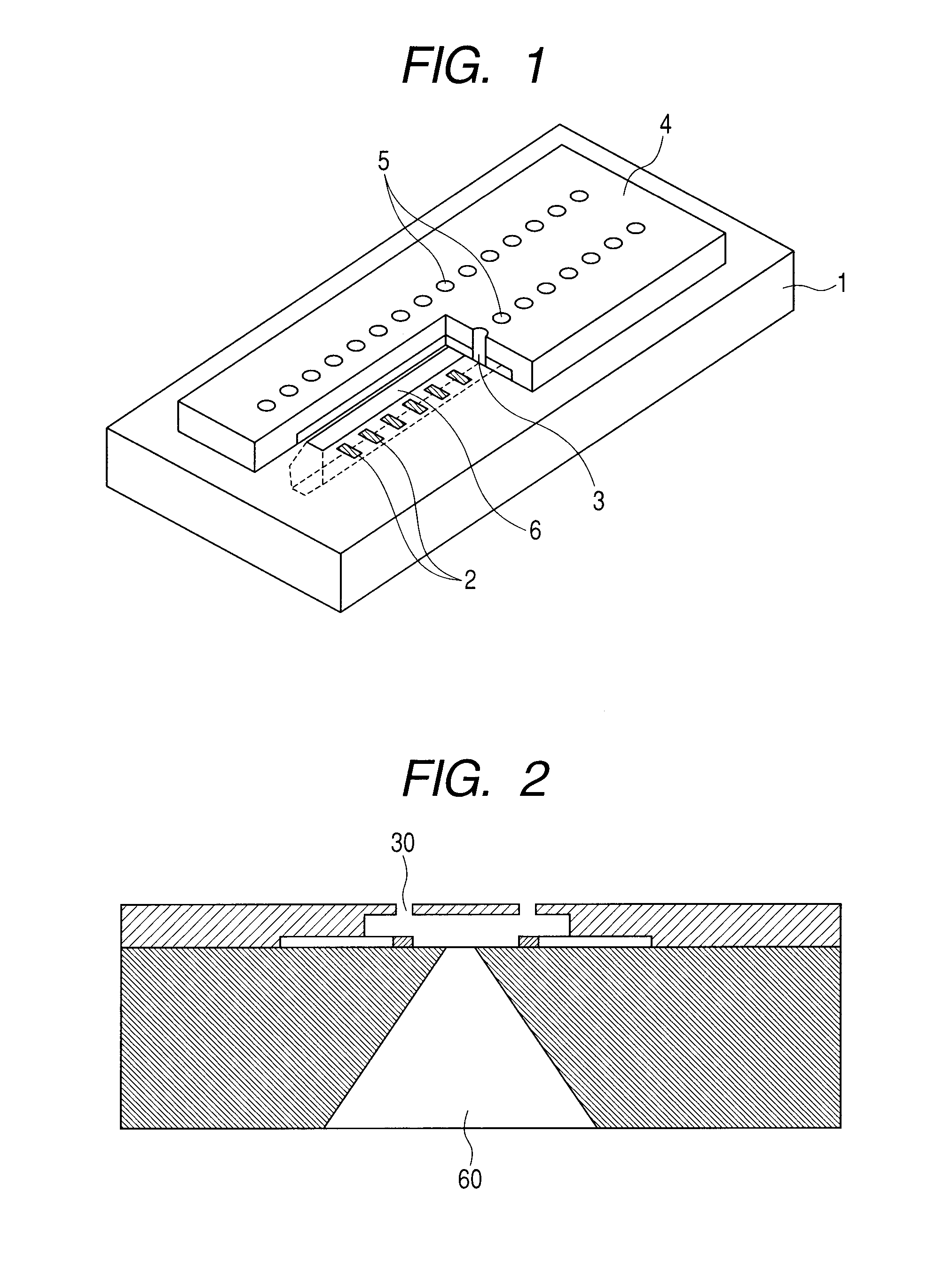
[0023]A method of manufacturing a substrate for an ink jet head in the present embodiment applies etching masks to both faces of a silicon substrate, forms through holes serving as leading holes in etching regions by, for example, laser beam machining, and then performs anisotropic etching from both the faces. The present embodiment will now be described in detail with reference to FIGS. 4A-4B and 5. FIGS. 4A and 4B are schematic process charts for describing an example of the method of manufacturing a substrate for a liquid discharge head, (a) to (f) of FIG. 4A are sectional views in a 4A-4A line in FIG. 5, and (a) to (f) of FIG. 4B are sectional views in a 4B-4B line. FIG. 5 is a schematic diagram illustrating an example of formation of etching mask patterns and leading holes seen from a first face side.

[0024]First, an etching mask material is formed on both faces (first and second faces) of a silicon substrate 1, and a first etching mask pattern 7 and a second etching mask patter...

embodiment 2

[0031]A method of manufacturing a substrate for an ink jet head in the present embodiment applies etching masks to both faces of a silicon substrate, forms non-through holes serving as leading holes alternately in a longitudinal direction in first and second faces by, for example, laser beam machining, and then performs anisotropic etching from both the faces. The present embodiment will now be described with reference to FIGS. 6A, 6B and 7.

[0032]First, first and the second etching mask patterns 7 and 8 which have an opening are formed in both the faces of the silicon substrate 1. In order to minimize the opening width of an ink supply hole formed by anisotropic etching that is a post step, the opening widths of openings in the first and second etching mask patterns can be made equal to each other.

[0033]Next, non-through holes as the leading holes are formed in the etching region ((b) in FIGS. 6A and 6B). The first recesses and the second recesses do not communicate with each other,...

embodiment 3

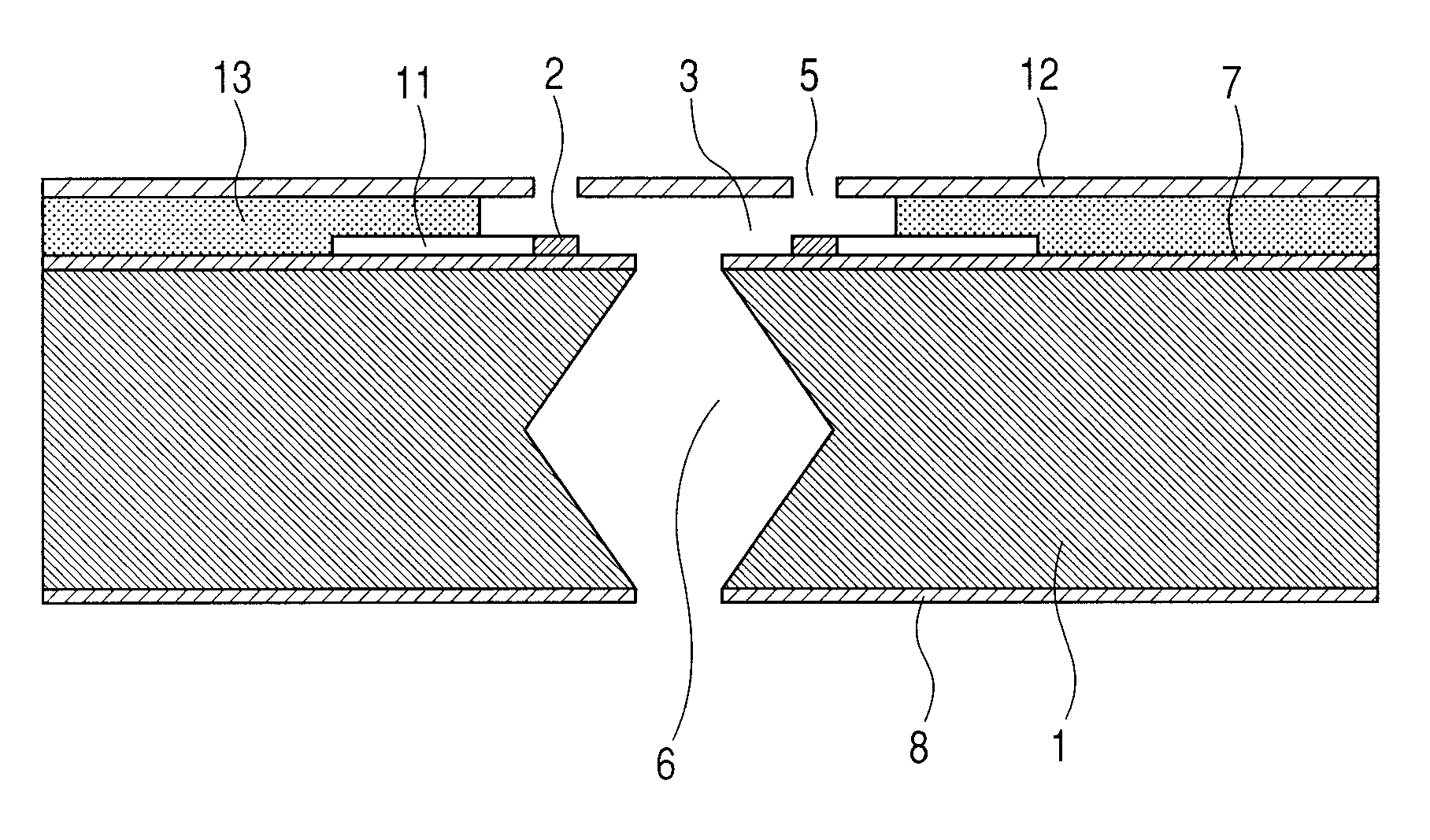
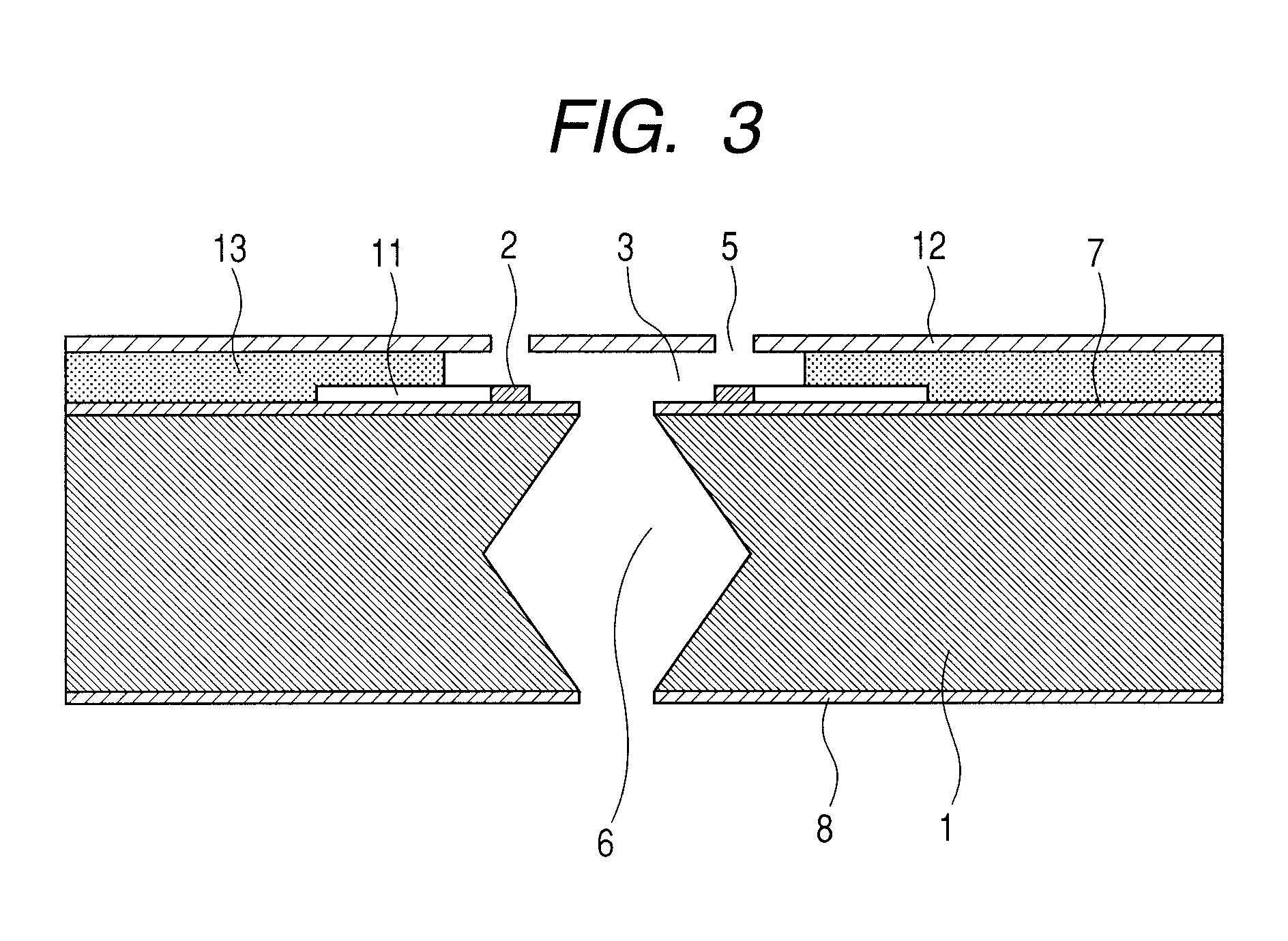
[0036]A cross-section of an ink jet head which has the substrate for an ink jet head manufactured by the manufacturing method of the present invention is illustrated in FIG. 3. The liquid discharge head is provided with a liquid supply port which communicates with discharge ports through which liquid is discharged and which supplies the liquid to a liquid flow channel having a discharge energy generating element for discharging the liquid. An example of the manufacturing method will now be described.

[0037]First, a discharge energy generating unit 2 for giving discharge energy to ink and wiring lines 11 for supplying an electric current to the discharge energy generating unit are formed on a substrate for an ink jet head.

[0038]Here, a method of fabricating an orifice plate 12 will be described. The orifice plate 12 can be fabricated using, for example, electroforming. The electroforming will now be simply described. First, a mandrel which has a shape complementary to a suitable orifi...


PUM


Abstract

A method of manufacturing a substrate for a liquid discharge head having a supply port passing through a silicon substrate provided with an energy-generating element generating the energy used to discharge a liquid and allowing liquid to be supplied to the energy-generating element, includes preparing a silicon substrate in which a first etching mask having a first opening is provided on a first face, and a second etching mask having a second opening is provided on a second face that is the rear face of the first face; forming a first recess towards the second face from the first face within the first opening, and forming a second recess towards the first face from the second face within in the second opening; and performing crystalline anisotropic etching using the first and second etching masks as masks from both of the first and second faces, to form the supply port.

Description

BACKGROUND OF THE INVENTION[0001]1. Field of the Invention[0002]The present invention relates to a method of manufacturing a substrate used for a liquid discharge head which applies energy to a liquid, such as ink, thereby discharging the liquid.[0003]2. Description of the Related Art[0004]Generally, an ink jet head is heated by a pressure generator, for example, a heater board for discharging ink, whereby components of an ink composition are evaporated to generate pressure to discharge ink. Additionally, generally, ink is supplied from the rear face of a substrate for an ink jet head in which the pressure generator is provided. For this reason, the ink jet head substrate is provided with an ink supply port for allowing a surface and a rear face to fluidly communicate with each other.[0005]As a method for forming an ink supply port in a substrate for an ink jet head, for example, U.S. Pat. No. 5,658,471 discloses using anisotropic etching by taking advantage of the features of a sin...

Claims


Application Information

Patent Timeline
Patent Type & Authority Applications(United States)
IPC IPC(8): H01L21/308
CPCB41J2/1603B41J2/1634B41J2/1631B41J2/1629
Inventor KOKUBO, SATOSHIKUBOTA, MASAHIKO
Owner CANON KK
Why Eureka
Try Eureka