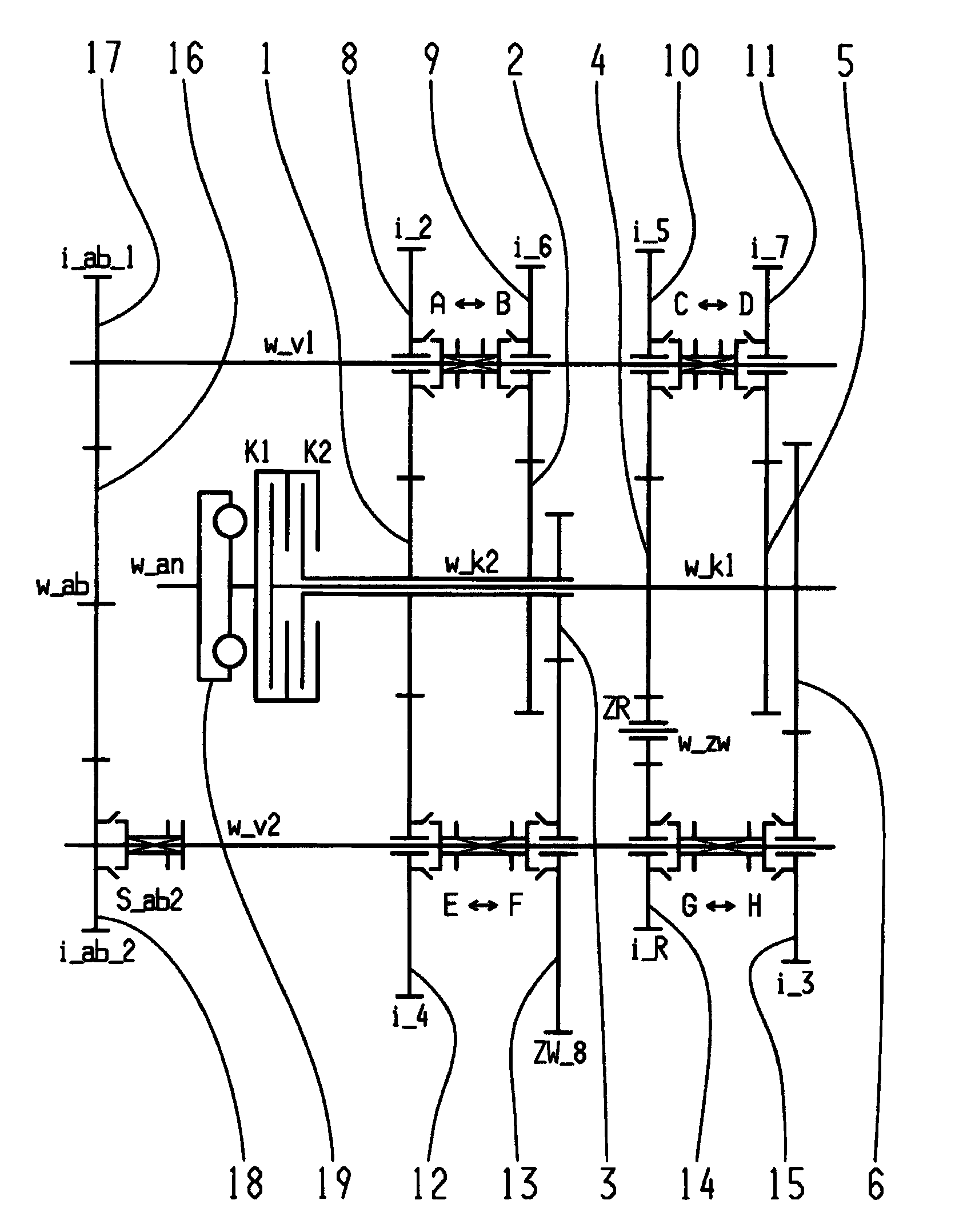
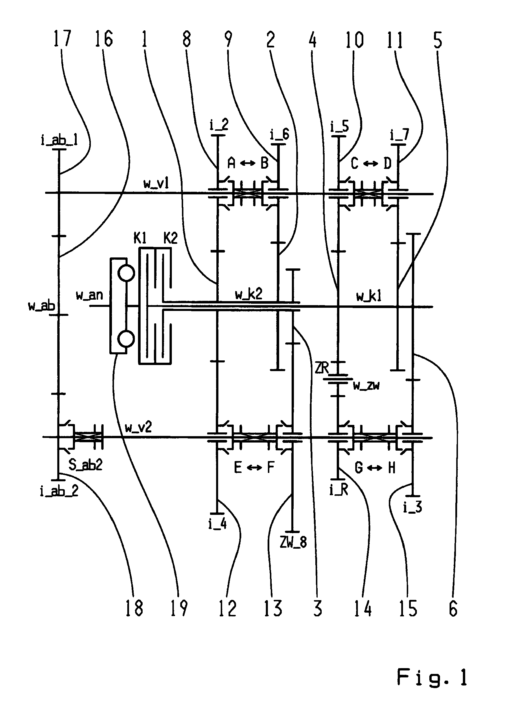
[0008]Accordingly, a construction-space-optimized double clutch transmission is proposed, whose input sides are connected to a
drive shaft, and whose output sides are each connected to one of for example two transmission input shafts which are situated coaxially to each other. The double clutch transmission comprises at least two countershafts or the like, on which toothed gearwheels designed as idler gears are rotatably carried, there being toothed gearwheels designed as fixed gears, at least part of which are engaged with the idler gears, placed in a rotationally fixed manner on the two transmission input shafts. Also provided are a number of
coupling devices for connecting an idler gear to a countershaft in a rotationally fixed manner. The double clutch transmission according to the invention has an output gear or constant
pinion on each of the countershafts, each of which is coupled with gearing of a drive shaft in order to connect the respective countershaft with the output drive, making a plurality of power-shiftable gears feasible.
[0012]To optimize the stepping in the double clutch transmission proposed according to the invention, it is also possible for example to replace a dual gear plane with two single gear planes, by replacing one fixed gear with two fixed gears. That makes it possible to achieve especially
harmonic, progressive gear stepping. It is also possible to replace two single gear planes with one dual gear plane.
[0020]In the double clutch transmission, the arrangement of the shift elements for coupling two particular idler gears can be varied so that the shift elements do not necessarily have to be placed between the idler gears that are to be coupled. Accordingly, other arrangement positions of the particular shift element are also conceivable, in order for example to optimize the linking to an
actuator system.
[0027]It is conceivable that the indicated positioning options for the toothed gearwheels may be varied, and also that the number of toothed gearwheels and the number of coupling devices may be changed, in order to realize even more power-shiftable or non-power-shiftable gears, as well as to save construction space and parts in the proposed double clutch transmission. In particular, fixed gears from dual gear planes can be divided into two fixed gears for two single gear planes. That makes it possible to improve step changes. In addition, it is possible to exchange the countershafts. The subtransmissions can also be exchanged; i.e., they are mirrored around a
vertical axis. In doing so, the hollow shaft and
solid shaft are exchanged. This makes it possible for example to place the smallest gearwheel on the
solid shaft, in order to further optimize the utilization of the available construction space. In addition, neighboring gear planes can be exchanged, for example, to optimize shaft flexing and / or to link optimally a shift actuating
system. Moreover, the particular placement position of the coupling devices at the gear plane can be varied. Furthermore, the direction of action of the coupling devices can also be changed.
[0029]Independent of the particular variant embodiments of the double clutch transmission, the drive shaft and the output shaft may preferably also not be situated coaxially with each other; this realizes an especially space-saving arrangement. For example, the shafts, which are thus positioned spatially one behind the other, may also be offset slightly relatively to each other. With this arrangement, a direct gear with a
transmission ratio of one is realizable by means of tooth engagement, and can be advantageously shifted to the sixth through ninth gears relatively freely. Other possible arrangements of the drive shaft and output shaft are also conceivable.
[0031]Advantageously, the lower forward gears and the reverse gears can be actuated by means of a start-up clutch or shifting clutch, in order to thereby concentrate higher loads on this clutch so that the second clutch can be designed for smaller construction space and lower cost. In particular, the gear planes can be situated in the proposed double clutch transmission so that the vehicle can be set in motion either by means of the inner transmission input shaft or of the outer transmission input shaft, and thus by means of whichever clutch is better suited in the particular case; this is also possible with a concentrically arranged, radially nested construction of the double clutch. Furthermore, the gear planes may be correspondingly arranged mirror-symmetrically, or may be exchanged.

