Double clutch transmission

Inactive Publication Date: 2010-10-14
ZF FRIEDRICHSHAFEN AG
View PDF9 Cites 12 Cited by
  • Summary
  • Abstract
  • Description
  • Claims
  • Application Information

AI Technical Summary

Benefits of technology

[0033]Advantageously, the lower forward gears and the reverse gears can be actuated by means of a start-up clutch or shifting a clutch in order to thereby concentrate higher loads on this clutch so that the second clutch can be designed for smaller construction space and lower cost. In particular, the gear planes can be arranged in the proposed double clutch transmission so that the vehicle can be

Problems solved by technology

This results in an undesirable lengthening of the construction length, in the axial direction, so that the possibility of installatio

Method used


Image

  • Double clutch transmission
  • Double clutch transmission
  • Double clutch transmission

Examples


Embodiment Construction

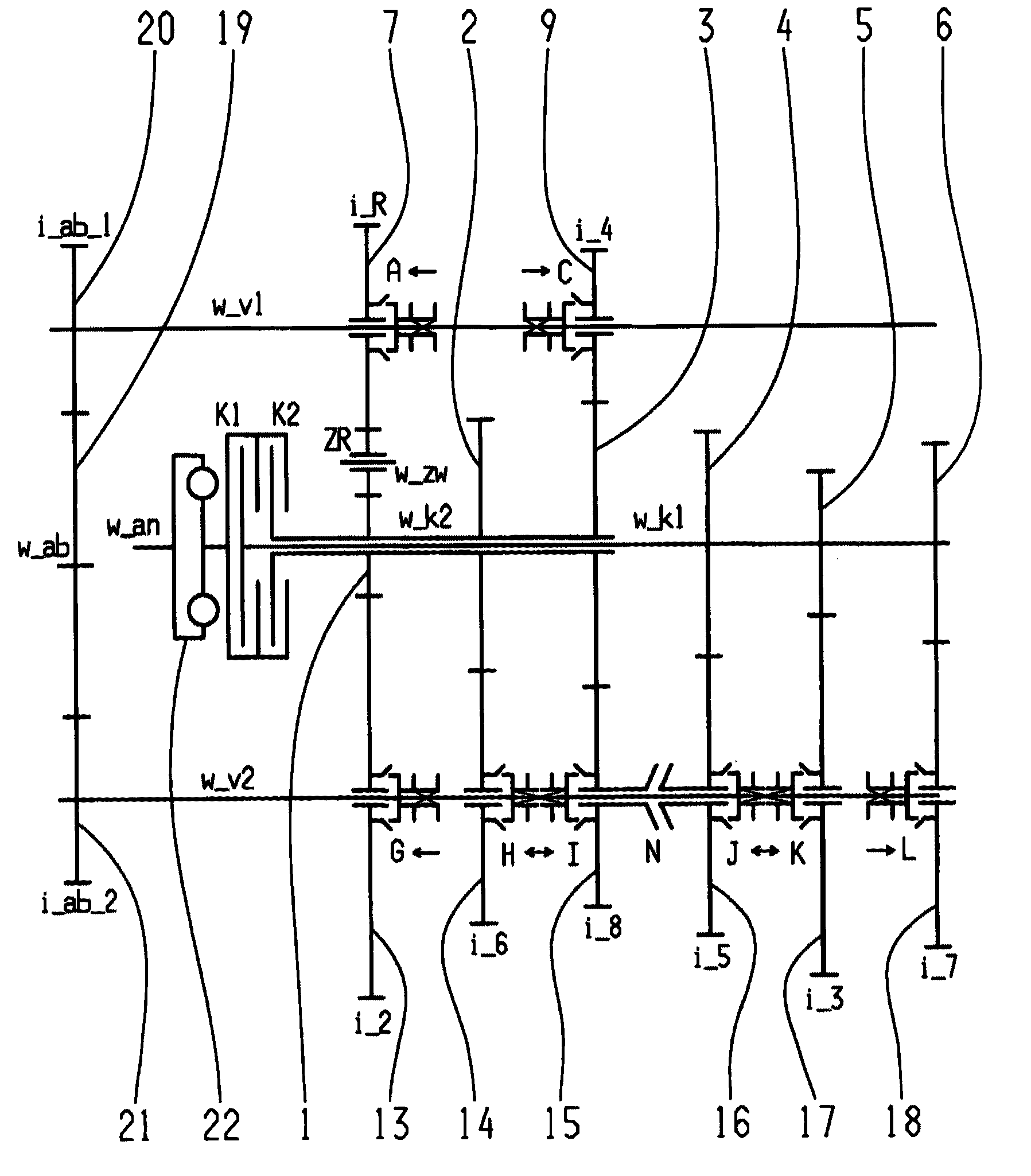
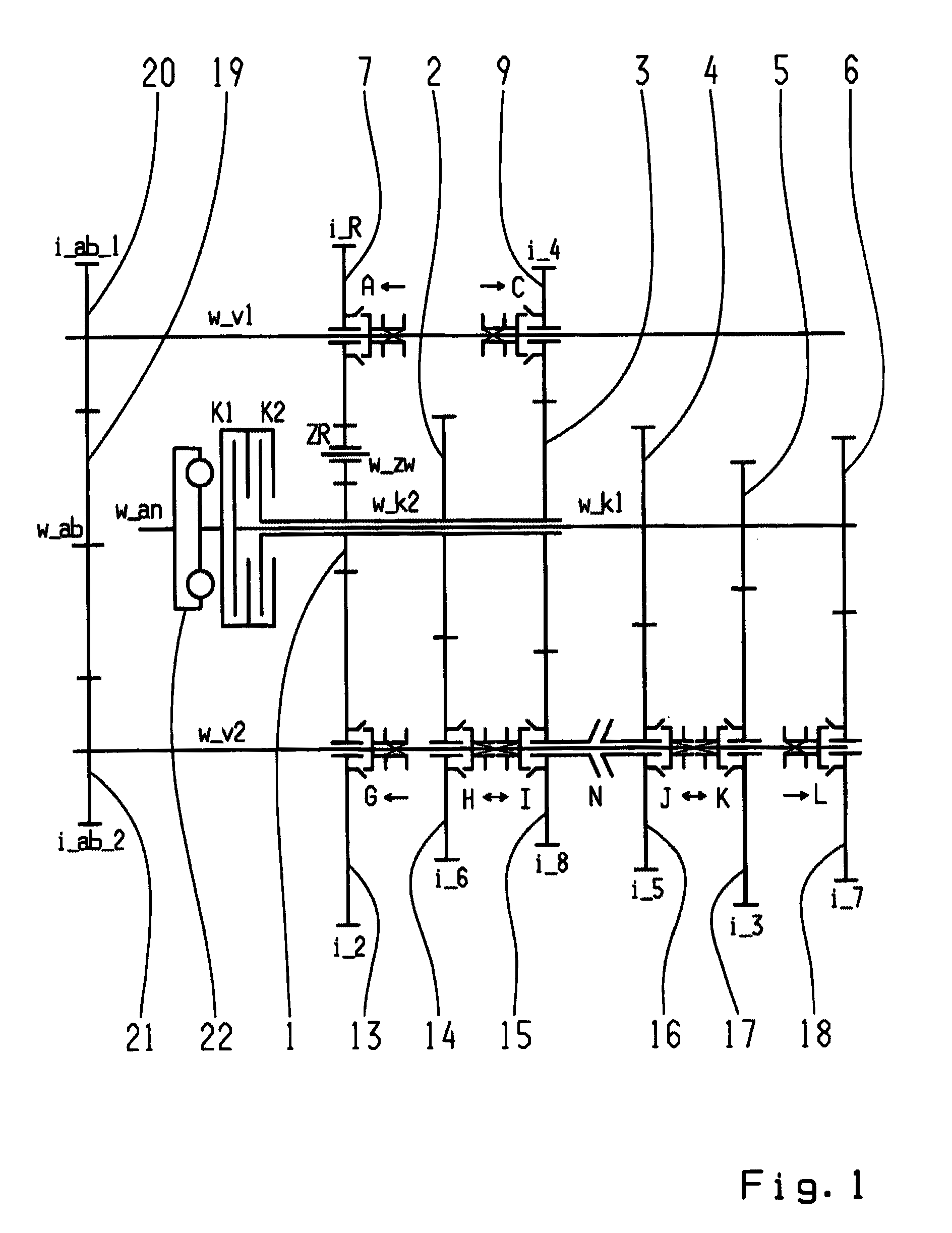
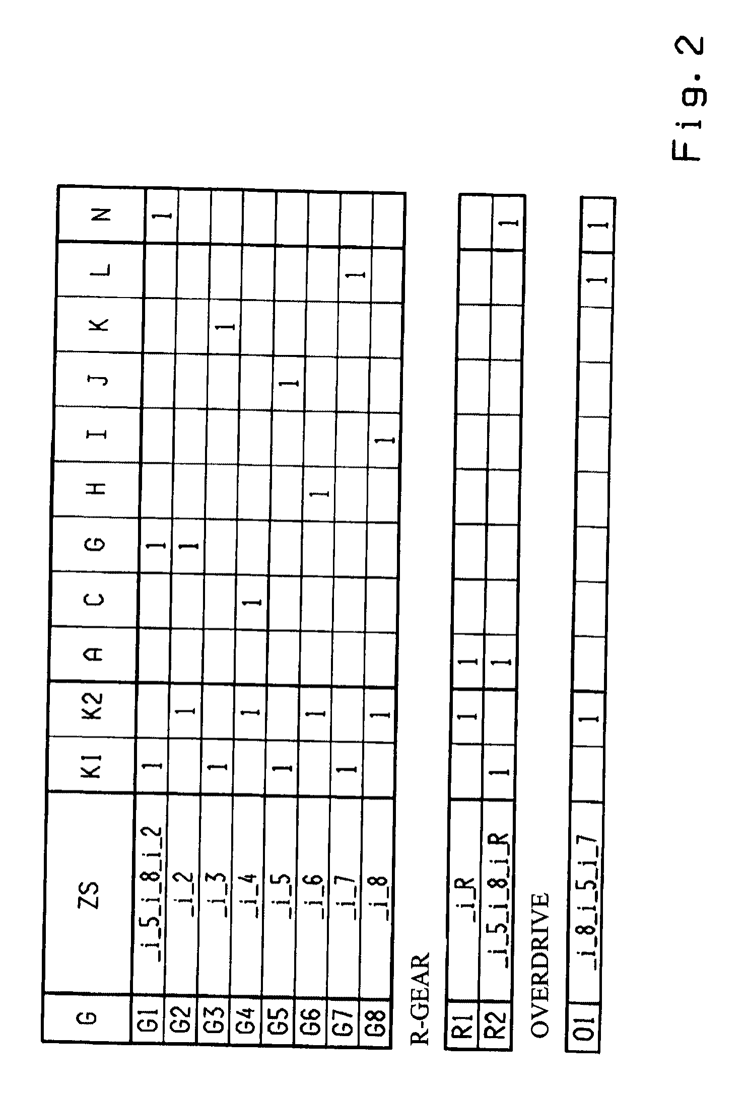
[0066]FIGS. 1, 3, 5, 7, 9, 11, 13, 15, 17, 19, 21, 23, 25, 27 and 29 each show a possible variant embodiment of an eight-speed double clutch transmission. The respective shift patterns for the different variant embodiments are depicted in chart form in FIGS. 2, 4, 6, 8, 10, 12, 14, 16, 18, 20, 22, 24, 26, 28 and 30.

[0067]The eight-speed double clutch transmission comprises two clutches K1, K2, whose input sides are connected to a drive shaft w_an and whose output sides are each connected to one of two respective transmission input shafts w_k1, w_k2, which are arranged coaxially with each other. In addition, a torsion vibration damper 22 can be placed on the drive shaft w_an. Furthermore, two countershafts w_v1, w_v2 are provided on which toothed gear wheels, in the form of idler gears 7, 8, 9, 10, 11, 12, 13, 14, 15, 16, 17, 18, are rotatably supported. Placed on the two transmission input shafts w_k1, w_k2 are rotationally fixed toothed gearwheels, designed as fixed gears 1, 2, 3, ...


PUM


Abstract

A double clutch transmission with inputs of two clutches (K1, K2) connected to a drive shaft (wan) and output sides connected to a respective transmission input shaft (w_k1 or w_k2) positioned coaxially to each other, at least two countershafts (w_v1, w_v2) each having toothed idler gearwheels (7, 9, 13, 14, 15, 16, 17, 18), toothed fixed gearwheels (1, 2, 3, 4, 5, 6) are positioned in a fixed manner on the two transmission input shafts (w_k1, w_k2), at least one shift element (N) is provided for connecting two toothed gear wheels with one another so that a plurality of power-shiftable forward gears (1, 2, 3, 4, 5, 6, 7, 8) and a shiftable reverse gear (R1, R2) is provided. A maximum of six gear planes (7-13, 2-14, 9-15, 4-16, 5-17, 6-18) are provided so that at least one power-shiftable winding path gear (G1, R2, O1) is shiftable by the shift element (N).

Description

[0001]This application claims priority from German patent application serial no. 10 2009 002 357.7 filed Apr. 14, 2009.FIELD OF THE INVENTION[0002]The present invention relates to a double clutch transmission.BACKGROUND OF THE INVENTION[0003]A six-speed or seven-speed double clutch transmission is known from published patent DE 103 05 241 A1. The double clutch transmission comprises two clutches, each of which is connected on its input side to the drive shaft, and on its output side to one of the two transmission input shafts. The two transmission input shafts are placed coaxially relative to each other. Furthermore, two countershafts are situated axially parallel to the two transmission input shafts, with their idler gears engaging fixed gears of the transmission input shafts. Moreover, coupling devices are held on countershafts so that they are axially movable and rotationally fixed in order to be able to shift the respective toothed gearwheels. The chosen transmission ratio is tr...

Claims


Application Information

Patent Timeline
IPC IPC(8): F16H3/20
CPCF16H3/006F16H2003/0826F16H2003/0931F16H2200/0026Y10T74/19233F16H2200/0065F16H2200/0086F16H2200/0091F16H2200/0095F16H2200/006F16H2003/0807
Inventor RIEGER, WOLFGANGRECKER, PHILIPGUMPOLTSBERGER, GERHARD
Owner ZF FRIEDRICHSHAFEN AG
Why Eureka
Try Eureka