Solar receiver utilizing carbon nanotube infused coatings

Inactive Publication Date: 2010-10-14
APPL NANOSTRUCTURED SOLUTIONS LLC
View PDF30 Cites 63 Cited by
  • Summary
  • Abstract
  • Description
  • Claims
  • Application Information

AI Technical Summary

Problems solved by technology

Although a high percentage of incident solar radiation may be initially absorbed, thermal absorbers can emit a high percentage as radiated heat, thereby lowering the effective collection of the solar energy.
However, the evacuated glass tubes generally used in conjunction with some of these coatings are costly to fabr

Method used


Image

  • Solar receiver utilizing carbon nanotube infused coatings
  • Solar receiver utilizing carbon nanotube infused coatings
  • Solar receiver utilizing carbon nanotube infused coatings

Examples


example i

[0128]This example shows the manufacture of CNT infused coating for use in a solar receiver and characterization of a model.

[0129]A CNT based coating can be manufactured by the following procedure:

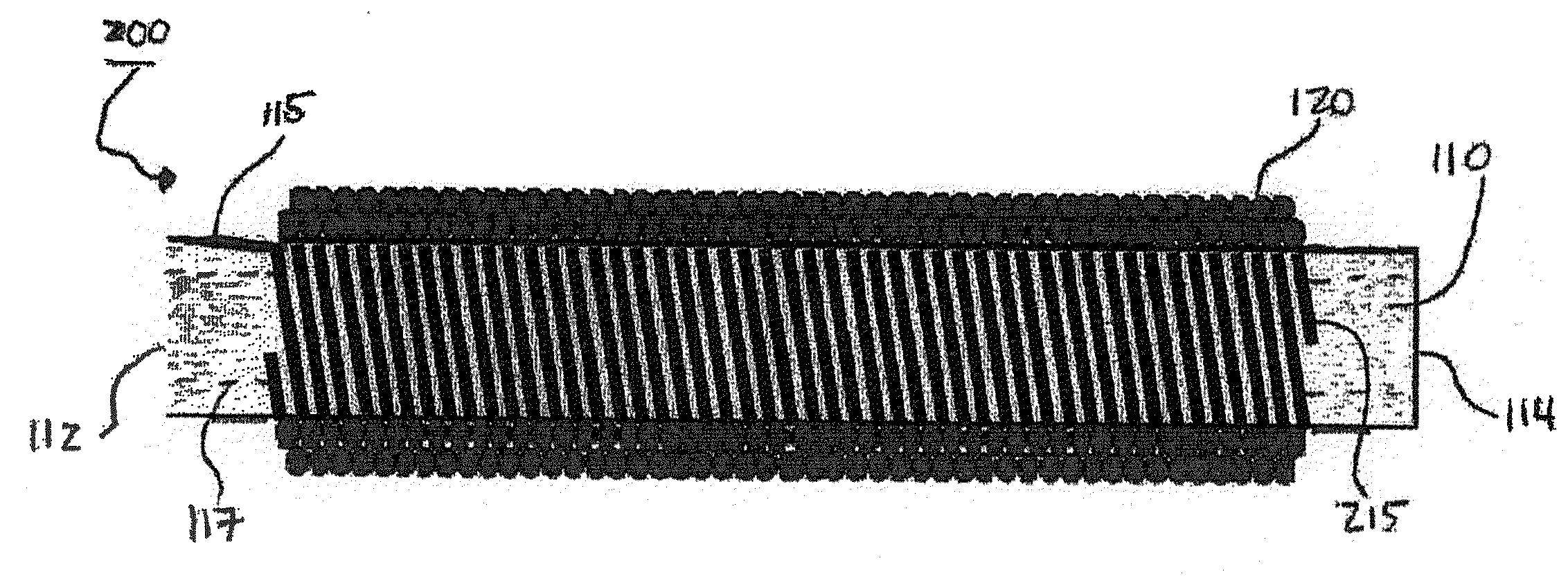
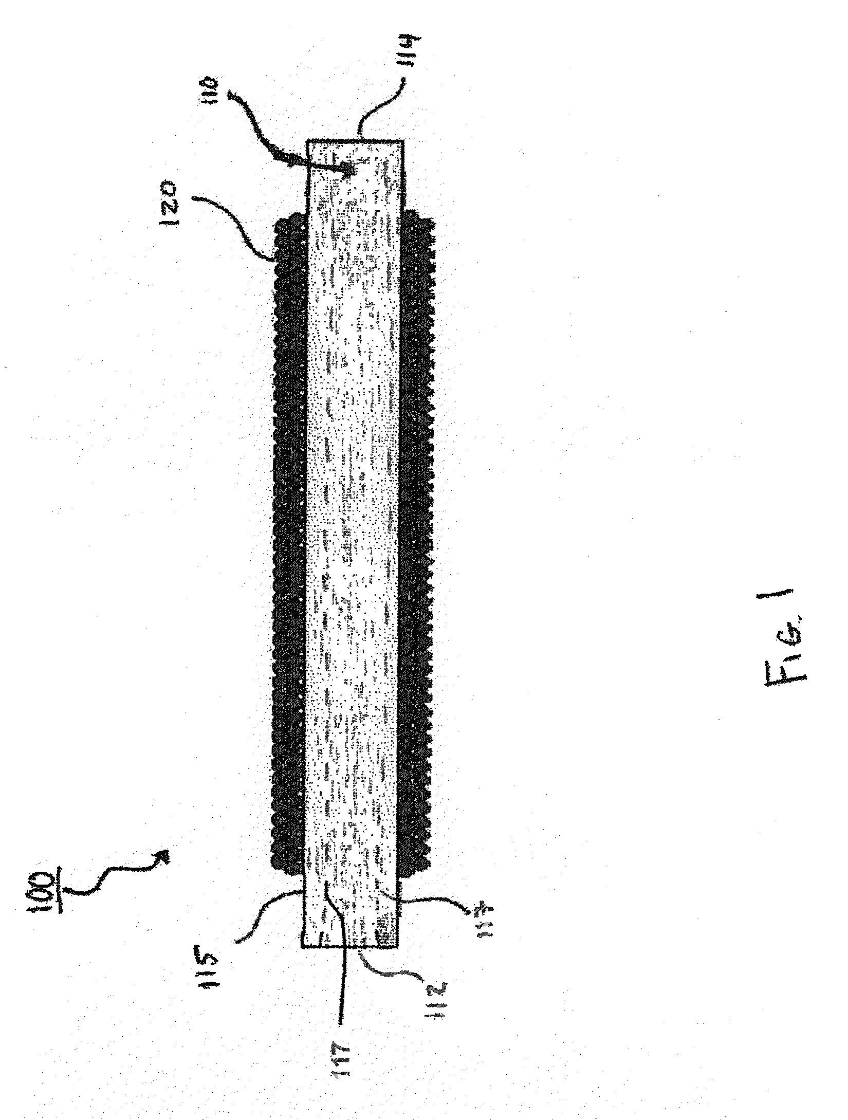
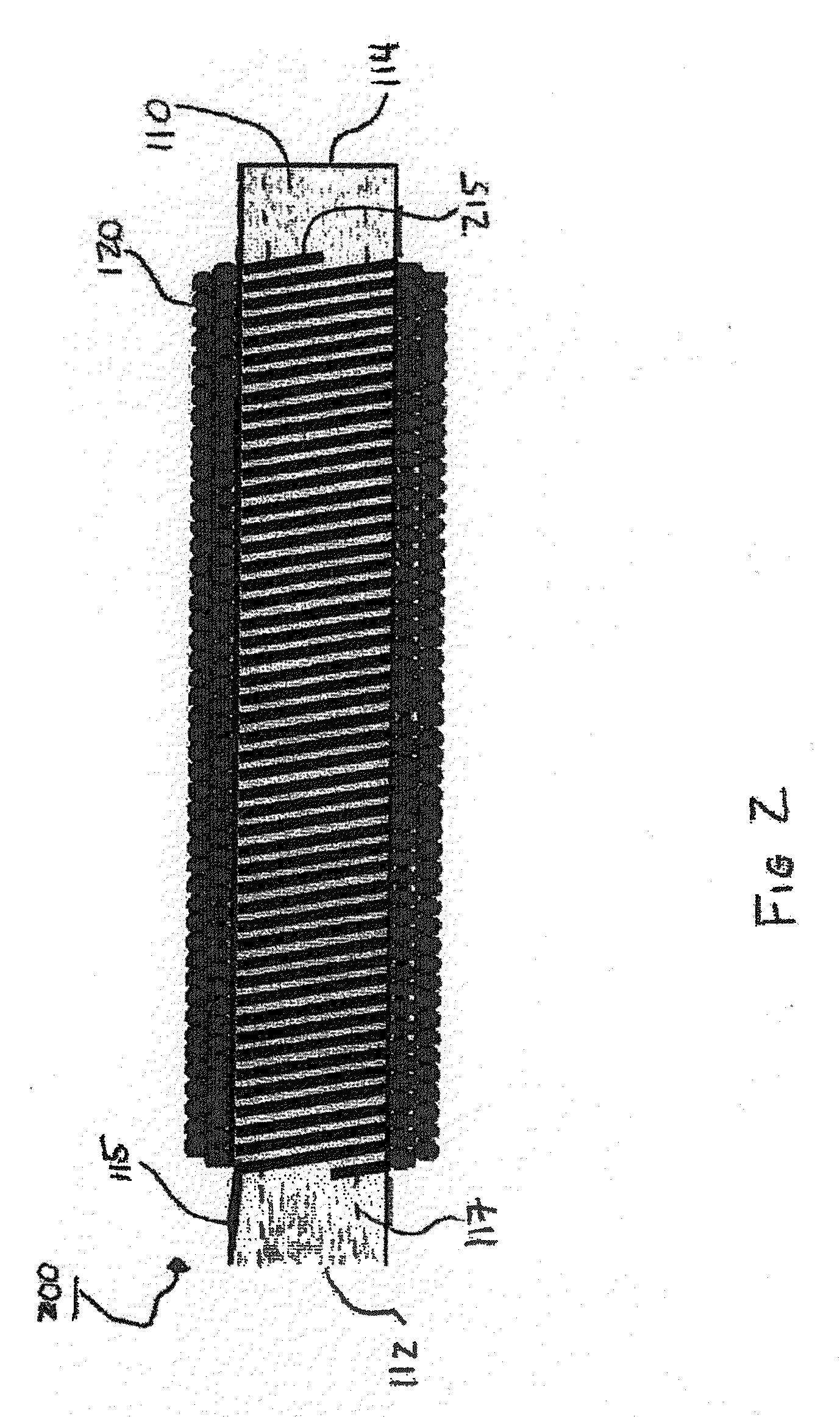
[0130]CNTs are infused to a carbon fiber tow (carbon fiber being exemplary) in a reel-to-reel system as outlined above. The CNT infused fiber tow is then wrapped over a heating element. Additional reflective layers are added as needed. A coating made by this procedure is expected to exhibit characteristics of being a solar selective coating. The exact characteristics of a coating employing CNT-infused fibers will depend on CNT length and density.

[0131]FIG. 16 shows the reflectivity data for a model of this CNT-infused fiber coating, namely Buckypaper, with an overlay of a theoretical ideal coating indicated as a dashed line. The CNT-infused fiber wrapped around a heating element has an arrangement of CNTs similar to Buckypaper. The arrangement of CNTs in Buckypaper are shown in the SEM ima...


PUM

PropertyMeasurementUnit
Energyaaaaaaaaaa
Heataaaaaaaaaa
Emissivityaaaaaaaaaa

Abstract

A solar receiver includes a heat absorbing element having an outer surface and an inner surface opposite the outer surface and a first coating including a carbon nanotube-infused fiber material in surface engagement with and at least partially covering the outer surface of the heat absorbing element. Solar radiation incident onto the first coating is received, absorbed, and converted to heat energy, and the heat energy is transferred from the first coating to the heat absorbing element. A multilayer coating for a solar receiver device includes a first coating that includes a CNT-infused fiber material and an environmental coating disposed on the first coating.

Description

STATEMENT OF RELATED APPLICATIONS[0001]This application claims priority under 35 U.S.C.119(e) to U.S. Provisional Application 61 / 167,386 filed Apr. 7, 2009.FIELD OF INVENTION[0002]The present invention relates in general to a solar receiver apparatus for receiving, absorbing, containing, and converting received electromagnetic radiation into heat energy.BACKGROUND[0003]Solar thermal collectors have been developed to harness the energy from solar radiation for various industrial processes, power generation and water heating applications. Solar radiation incident onto the earth's surface has an estimated power density of about 1 kW / m2 and wavelengths ranging from about 200 nanometers (nm) for ultraviolet (UV) radiation to about 2500 nm for infrared (IR) radiation. Solar thermal collectors generally include a reflector to focus the solar radiation onto a thermal receiver. The thermal receiver converts the photonic energy of the solar radiation into thermal energy of a heat transfer flu...

Claims


Application Information

Patent Timeline
IPC IPC(8): F24J2/32F24J2/48F24S10/50F24S10/70F24S10/95
CPCC23C26/00C23C28/42C23C30/00F24J2/07F24J2/32F24J2/4652F24J2/485Y02E10/41Y02E10/44Y02T50/67C23C28/04C23C28/322C23C28/324C23C28/34C23C28/345C23C28/3455C23C28/00F24S70/30F24S20/20F24S70/225F24S10/95Y02E10/40Y02T50/60
Inventor SHAH, TUSHAR K.MALECKI, HARRY C.ADCOCK, DANIEL J.HEICK, KRISTOPHER
Owner APPL NANOSTRUCTURED SOLUTIONS LLC
Why Eureka
Try Eureka