Generation of steam from solar energy

Inactive Publication Date: 2010-10-14
VICTORY ENERGY OPERATIONS
View PDF23 Cites 45 Cited by
  • Summary
  • Abstract
  • Description
  • Claims
  • Application Information

AI Technical Summary

Benefits of technology

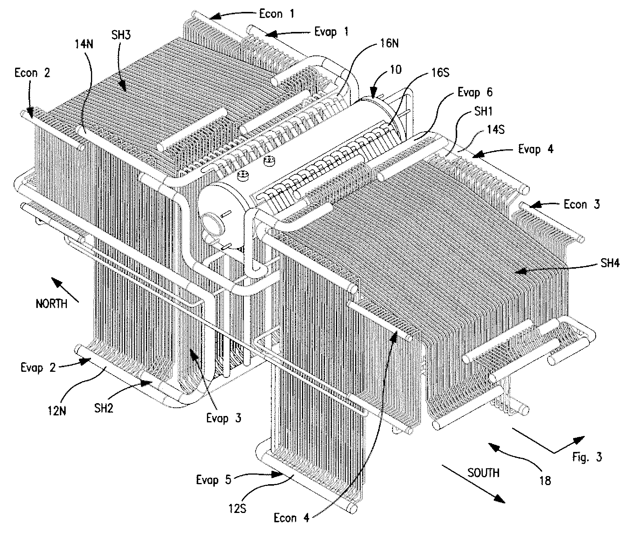
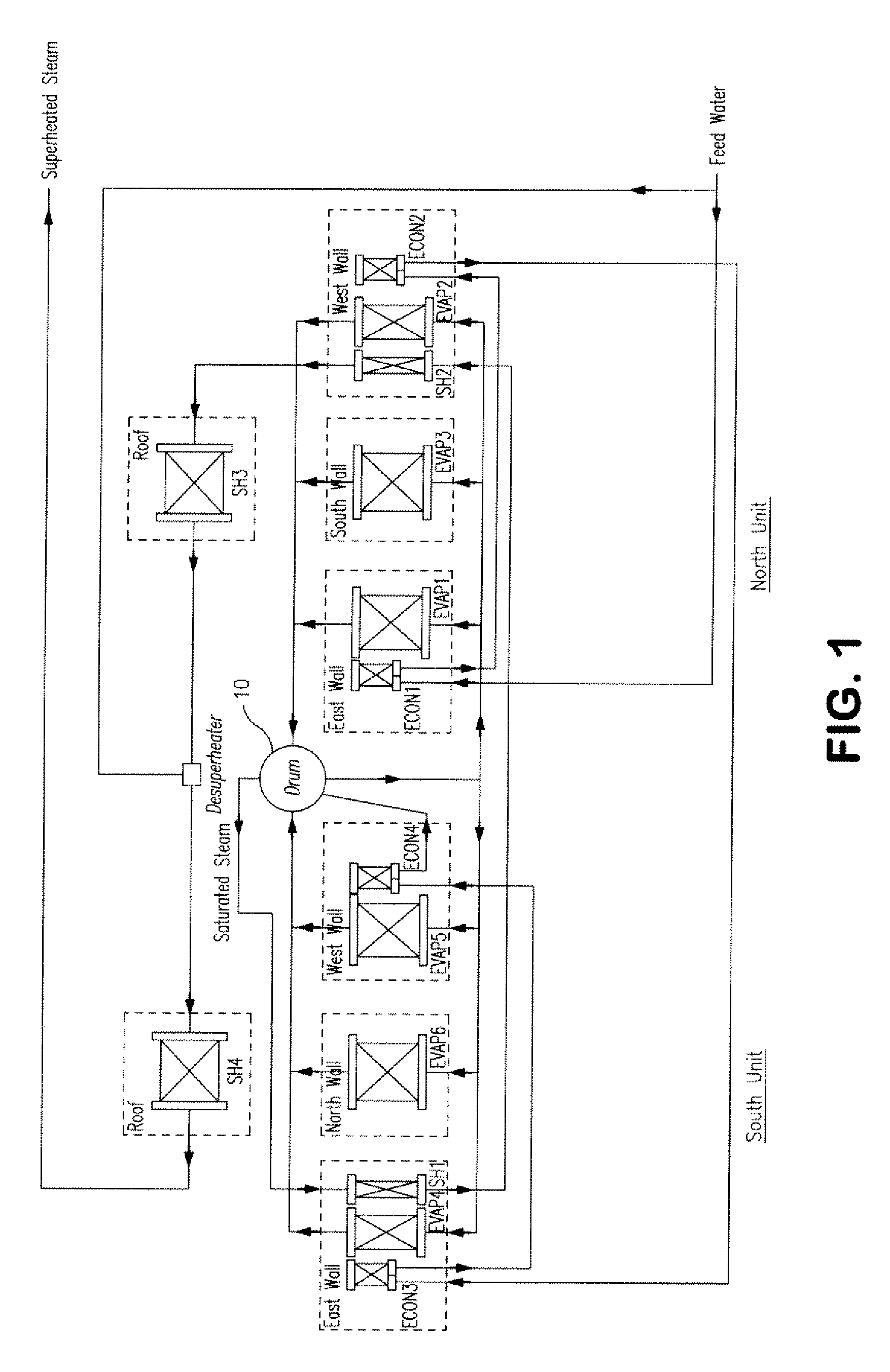
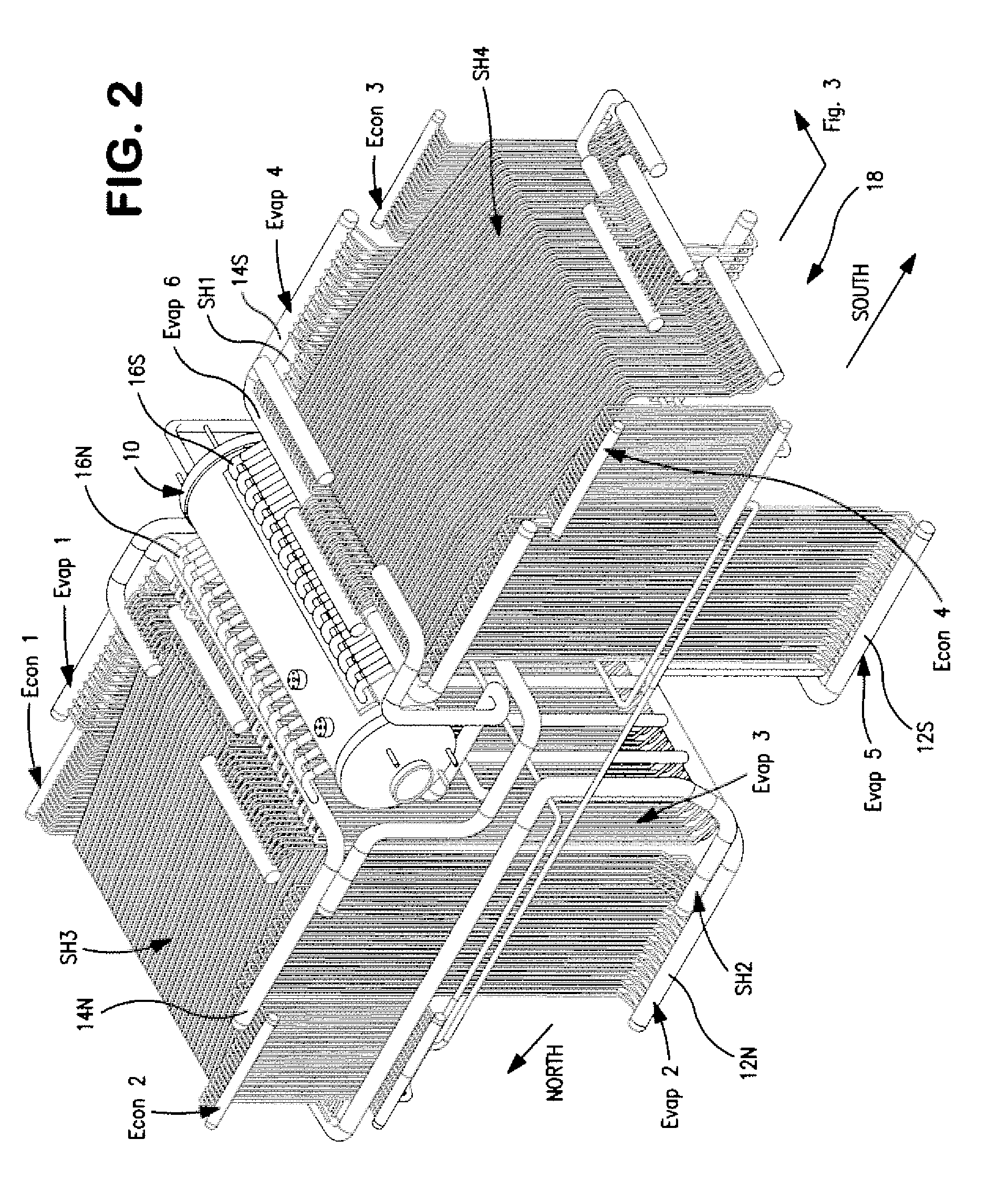
[0008]In a preferred embodiment, two of the cavity-type solar energy receivers are positioned as mirror images, one facing north and the other south, both receiving concentrated solar energy from mirrors at ground level (a heliostat) reflecting light to the solar energy receivers mounted on a tower. A steam drum serving both receivers is mounted between them and within an enclosure for both receivers. In combination, the panels of tubes form a cavity within which concentrated solar energy is used to generate high pressure steam. Between the cavity formed by panels of tubes and the surrounding

Problems solved by technology

However, in applying solar energy only radiant heat is available,

Method used


Image

  • Generation of steam from solar energy
  • Generation of steam from solar energy
  • Generation of steam from solar energy

Examples


Embodiment Construction

[0012]Design Problems

[0013]There are problems unique to the generation of high pressure steam from concentrated solar energy. They begin with the location of the steam generating equipment. Since the steam boiler and associated piping will be located atop a tower of one hundred feet or so, the weight of the equipment and environmental (e.g. wind and earthquake) forces on it must be accounted for in the design. Also, because access to the boiler equipment will be limited, especially when it is receiving the sun's rays reflected from mirrors at ground level, the design must be reliable and operated from a remote location. Some other problems are unique to the steam generating equipment itself.

[0014]Of first importance is the availability of solar energy. Since the amount of the sun's energy that falls on an array of mirrors will vary during the day and with the time of year, the amount of the sun's energy that can be reflected to the solar boiler equipment will change from minute to m...


PUM


Abstract

A cavity-type solar energy receiver for generating high pressure steam, which includes panels of tubes defining a cavity within an outer enclosure. Concentrated solar energy provided by a heliostat enters the cavity opening in the enclosure and evaporates water within some of the tube panels. The evaporating tubes receive hot water from a steam drum by natural circulation and return a mixture of steam and hot water to the steam drum. Additional tube panels are positioned to receive reflected solar energy, which is used to preheat feed water and to superheat steam.

Description

CROSS REFERENCE TO RELATED APPLICATIONS[0001]This application claims the benefit of priority of U.S. Provisional Applications 61 / 212,390 filed Apr. 10, 2009 and 61 / 217,425 filed May 29, 2009 and incorporated herein by reference.BACKGROUND OF THE INVENTION:[0002]This invention relates to recovering solar energy in the form of steam, which may be used to generate electricity or in industrial processes. More particularly, the invention includes a novel method and apparatus for converting solar energy to high pressure steam; that is, a steam boiler that employs the sun's rays to produce steam.[0003]Many proposals have been made to focus the sun's rays to concentrate solar energy. Electricity can be made directly by using heat engines that receive heat from focusing the sun's rays with a solar dish. Generating electricity with hot heat transfer liquids has been demonstrated for some years. Parabolic trough systems focus the sun's rays on receiving tubes running through the trough that ca...

Claims


Application Information

Patent Timeline
IPC IPC(8): F24J2/10F24J2/24F24S10/70F24S23/70
CPCF22B1/006F22B35/02Y02E10/46F24J2002/1071Y02E10/41F24J2/07F24S20/20F24S2023/86Y02E10/40
Inventor VISKUP, JR., JOHN C.LIN, BOCHUAN
Owner VICTORY ENERGY OPERATIONS
Why Eureka
Try Eureka