Desulfurization and denitrification integrated device

A technology of desulfurization and denitrification and desulfurization devices, which is applied in the field of desulfurization and denitrification, can solve the problems of high manufacturing cost and large equipment footprint, and achieve the effects of saving operating costs, small flue gas flow resistance, and heat loss control

Pending Publication Date: 2020-08-18
北京晨晰环保工程有限公司 +1
View PDF2 Cites 0 Cited by
  • Summary
  • Abstract
  • Description
  • Claims
  • Application Information

AI Technical Summary

Problems solved by technology

[0007] The technical problem to be solved by the present invention is: the desulfurization device and the denitrification system in the existing dry desulfurization-SCR denitrification technology are independent and separated equipment, which are connected by an intermediate device, so that the equipment occupies a large area and the manufacturing cost is high.

Method used


Image

  • Desulfurization and denitrification integrated device
  • Desulfurization and denitrification integrated device
  • Desulfurization and denitrification integrated device

Examples


Embodiment 1

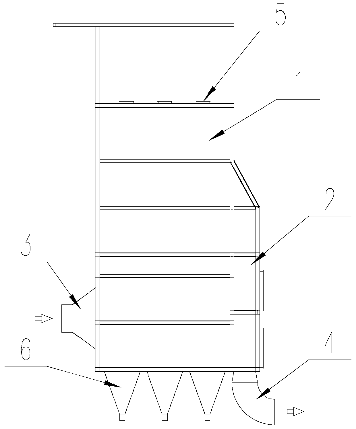
[0038] Such as Figure 1 to Figure 3 As shown, a desulfurization and denitrification integrated device includes a desulfurization device 1 and a denitrification system 2, the denitrification system 2 is arranged adjacent to the desulfurization device 1, and a flue gas inlet 3 is provided under the side of the desulfurization device 1, so A flue gas outlet 4 is provided under the side of the denitrification system 2, and the desulfurization device 1 and the denitrification system 2 are connected through a desulfurization flue gas outlet 7. The desulfurization flue gas outlet 7 is located above the side of the desulfurization device 1 and is located at The opposite side of the flue gas inlet 3.

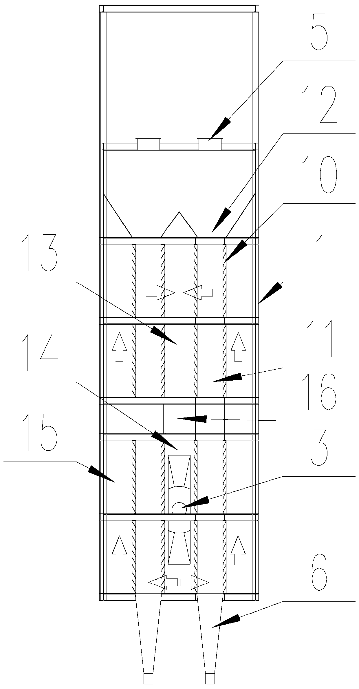
[0039] The desulfurization device 1 includes a desulfurization agent feeding port 5 and a desulfurization grid 10 , the desulfurization grids 10 are arranged at intervals to form a desulfurizing agent filling chamber 11 , and the desulfurizing agent feeding port 5 communicates with the de...

Embodiment 2

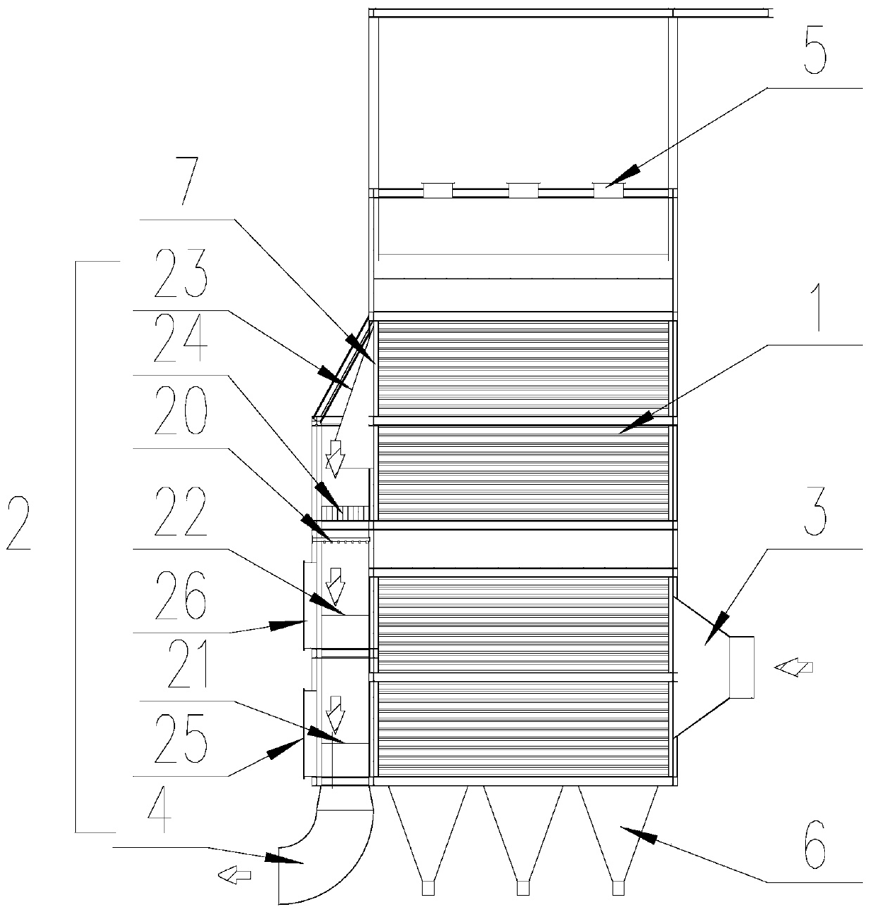
[0047] The difference between this embodiment and Embodiment 1 is that a denitrification catalyst standby layer 22 is also provided between the ammonia injection grid 20 and the catalyst placement layer, and the denitration catalyst standby layer 22 is provided with a second transfer gate 26. When the amount of catalyst is small and the catalytic effect becomes poor, a spare catalyst can be added to the denitration catalyst spare layer 22 through the second transfer gate 26 to promote the normal progress of the denitration reaction.

Embodiment 3

[0049] The difference between this embodiment and Embodiment 2 is that the denitrification system 2 is also provided with a flow guide device 23 and a rectification grid 24, the flow guide device 23 is arranged at the desulfurization flue gas outlet 7, and the rectification grid The grid 24 is located below the deflector 23 and above the ammonia injection grid 20 .

[0050] The specific operation process is:

[0051] The desulfurizer is transported to the top of the desulfurization tower with a ton bag, and the ton bag is sent to the top of the desulfurization device 1 through an electric hoist, and then the ton bag is manually opened, so that the desulfurizer automatically enters through the desulfurizer feeding port 5 and through the material guide port 12 The desulfurizing agent filling cavity 11 can also be automatically loaded by bucket lifting and conveying devices. During the specific treatment, after the flue gas from the coke oven enters the desulfurization device 1 ...


PUM


Abstract

The invention discloses a desulfurization and denitrification integrated device. The problems that in an existing dry desulfurization-SCR denitration technology, a desulfurization device and a denitration system are independently separated equipment and are connected via an intermediate device, therefore, the equipment is large in occupied area and high in manufacturing cost. The desulfurization and denitrification integrated device comprises a desulfurization device and a denitration system which are arranged adjacently, wherein the desulfurization device is provided with a flue gas inlet, the denitration system is provided with a flue gas outlet, and the desulfurization device and the denitration system are communicated through the desulfurized flue gas outlet. The device has the advantages of integration of desulfurization, denitrification and dust removal, small equipment occupied area, low manufacturing cost, good desulfurization, denitrification and dust removal effects and the like.

Description

technical field [0001] The invention relates to the technical field of desulfurization and denitrification, in particular to an integrated desulfurization and denitrification device. Background technique [0002] According to the national environmental protection requirements, the flue gas discharge must be desulfurized and denitrified, so that the flue gas meets the national and local environmental protection requirements and meets the emission standards. [0003] The existing desulfurization methods include wet desulfurization, semi-dry desulfurization and dry desulfurization. The wet desulfurization is to suspend calcium carbonate and other desulfurization agents in water to form a slurry and contact the exhaust gas in the absorption tower to achieve the purpose of desulfurization. Semi-dry desulfurization uses dry calcium hydroxide as an absorbent, and through multiple recirculation of the absorbent, the contact time between the absorbent and the flue gas is prolonged in...

Claims


Application Information

Patent Timeline
Patent Type & Authority Applications(China)
IPC IPC(8): B01D53/75B01D53/81B01D53/50B01D53/90B01D53/56B01D46/30
CPCB01D46/30B01D53/508B01D53/75B01D53/81B01D53/8631B01D53/90B01D2251/2062B01D2258/0283
Inventor 于立波张涛冯薪自张超贾莹张玉生李孟龙张明张德生
Owner 北京晨晰环保工程有限公司
Why Eureka
Try Eureka