
Heat dissipation device with fan holder

a technology of heat dissipation device and fan holder, which is applied in the direction of semiconductor devices, lighting and heating apparatus, basic electric elements, etc., can solve the problems of damage to computer components, laborious and time-consuming unscrewing and screwing operation, and large heat generation of computer electronic devices such as central processing units

Inactive Publication Date: 2010-10-14
FU ZHUN PRECISION IND SHENZHEN +1
View PDF8 Cites 5 Cited by
  • Summary
  • Abstract
  • Description
  • Claims
  • Application Information

AI Technical Summary

Benefits of technology

[0005]Generally, in order to improve heat dissipation efficiency of a heat sink, a fan is desired to direct airflow onto the heat sink. It is generally to fix the fan onto the heat sink with screws. Furthermore, it is necessary to disassemble the fan from the heat sink when dust particles accumulate in the fan and the heat sink, whereby the fan and the heat sink can be cleaned. Otherwise, heat dissipation efficiency of the heat sink will be decreased and a lifespan of the fan will be shortened. After cleaning of the fan and heat sink, it is required to assemble the fan to the heat sink again. Both the disassembling and assembling require rotating the screws by using a screwdriver. Such an unscrewing and screwing operation is laborious and time consuming. In addition, it is possible that the screws or screwdriver may drop to cause damages to computer components in the process of assembling and disassembling.

Problems solved by technology

It is well known that during operation computer electronic devices such as central processing units (CPUs) can generate large amounts of heat.
Such an unscrewing and screwing operation is laborious and time consuming.
In addition, it is possible that the screws or screwdriver may drop to cause damages to computer components in the process of assembling and disassembling.

Method used


Image

  • Heat dissipation device with fan holder
  • Heat dissipation device with fan holder
  • Heat dissipation device with fan holder

Examples


Embodiment Construction

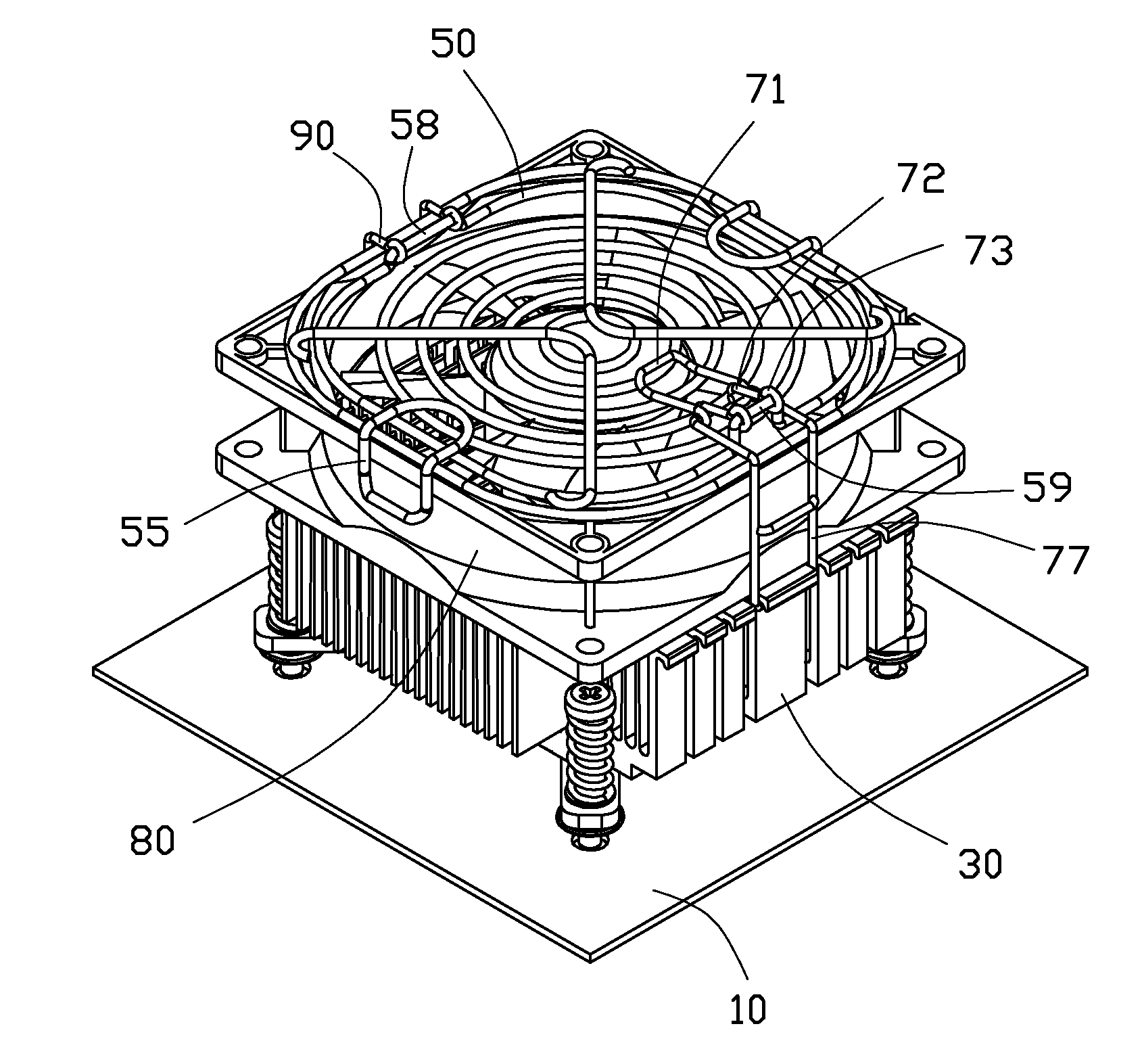
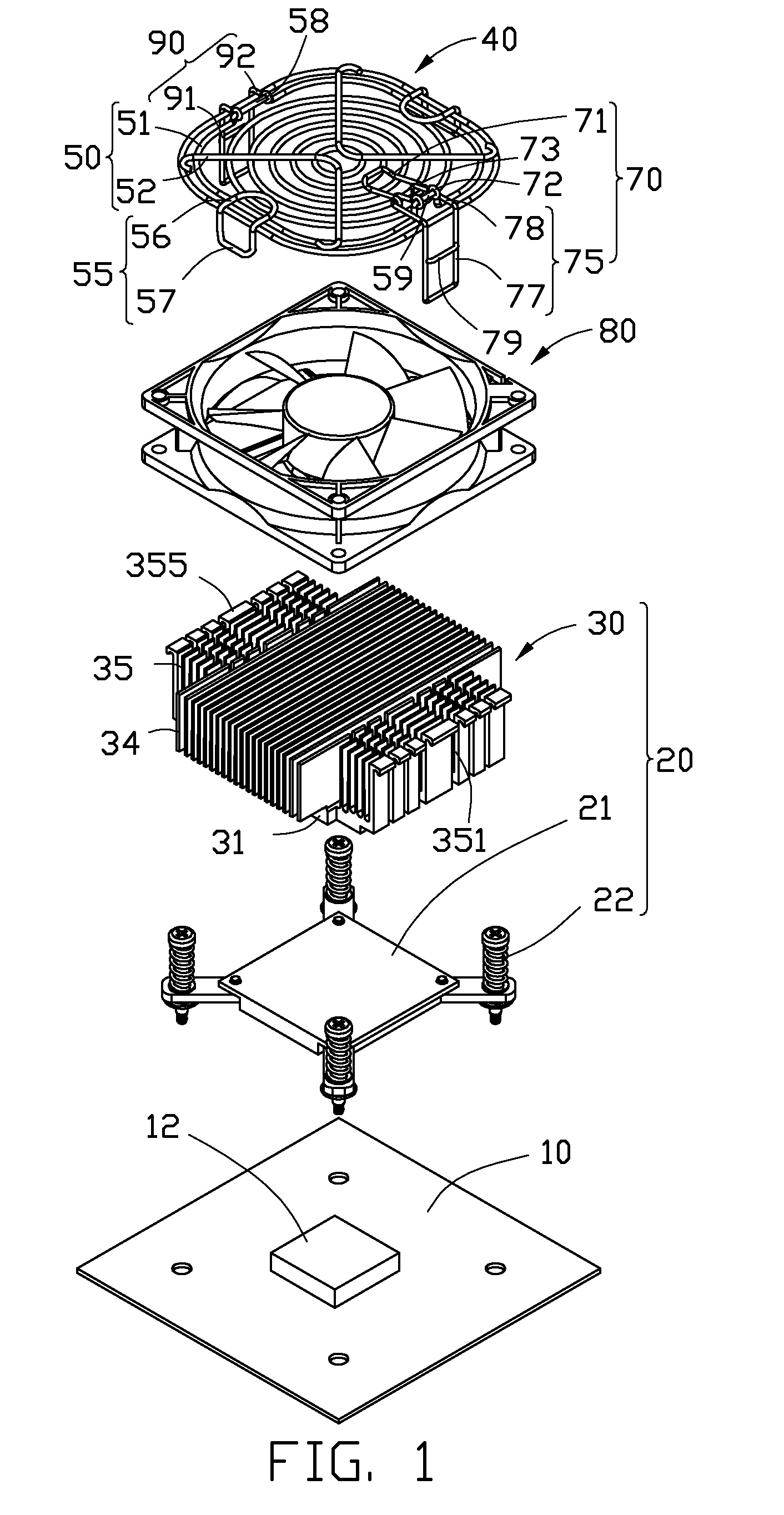
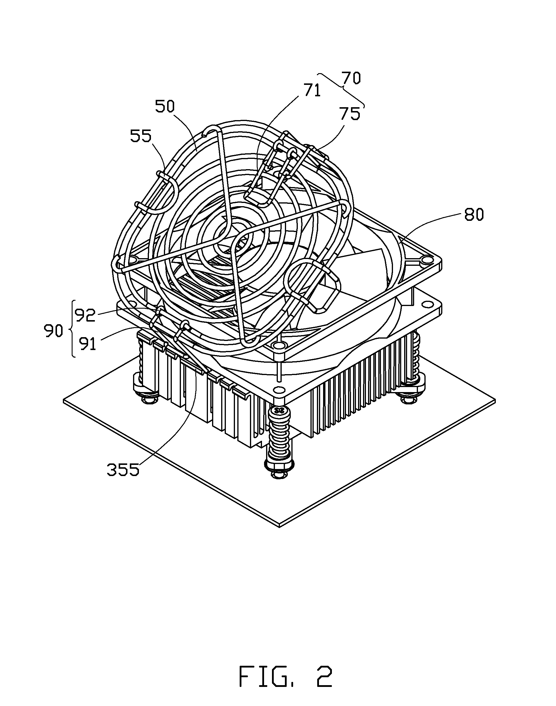
[0012]Referring to FIG. 1, a heat dissipation device in accordance with an embodiment of the disclosure is secured to a heat-generating electronic component 12 mounted on a printed circuit board 10. The heat dissipation device comprises a heat sink assembly 20, a fan holder 40, and a fan 80 mounted on the heat sink assembly 20 by the fan holder 40.

[0013]The heat sink assembly 20 comprises a heat spreader 21 attached on the heat-generating electronic component 12, a plurality of fasteners 22 mounting the heat spreader 21 on the printed circuit board 10, and a heat sink 30 attached on the heat spreader 21.

[0014]The heat sink 30 is integrally made of metal having a good thermal conductivity, such as copper, aluminum or an alloy thereof. In this embodiment, the heat sink 30 is made of aluminum and formed by extrusion. The heat sink 30 comprises a base 31, a plurality of first fins 34 and second fins 35 integrally extending upwardly from a top face of the base 31. The first fins 34 are p...


PUM


Abstract

A heat dissipation device includes a heat sink, a fan mounted on the heat sink and a fan holder mounting the fan on the heat sink. The fan holder includes a fan guard resting on the fan, a first clip and a second clip pivotably attached to the fan guard and engaged with the heat sink. The first clip includes an actuating member pivotably connecting to the fan guard and a buckling member pivotably connecting to the actuating member. The buckling member has a clasp engaging the heat sink at a locked position. The buckling member moves with a pivotal movement of the actuating member relative to the fan guard to leave the locked position and reach an unlocked position.

Description

BACKGROUND[0001]1. Technical Field[0002]The disclosure relates to a heat dissipation device and, more particularly, to a heat dissipation device having a fan holder for securing a fan onto a heat sink of the heat dissipation device, wherein the fan holder can be easily assembled to and disassembled from the heat sink to mount / dismount the fan to / from the heat sink.[0003]2. Description of Related Art[0004]It is well known that during operation computer electronic devices such as central processing units (CPUs) can generate large amounts of heat. The heat must be quickly removed from the electronic device to prevent it from becoming unstable or being damaged. Typically, a heat sink is attached to an outer surface of the electronic device to absorb heat from the electronic device, and the heat absorbed by the heat sink is then dissipated to ambient air.[0005]Generally, in order to improve heat dissipation efficiency of a heat sink, a fan is desired to direct airflow onto the heat sink....

Claims


Application Information

Patent Timeline
IPC IPC(8): F28D15/00F28F13/12
CPCH01L23/467H01L2924/0002H01L2924/00
Inventor CAO, LEILI, MIN
Owner FU ZHUN PRECISION IND SHENZHEN
Learn More