Armature core, armature, rotary electric machine and compressor

a technology of armature core and armature, which is applied in the direction of machines/engines, magnetic circuit shapes/forms/construction, liquid fuel engines, etc., can solve the problems of increasing copper loss, and achieve the effects of reducing magnetic resistance, reducing eddy current, and widening width

Inactive Publication Date: 2010-10-14
DAIKIN IND LTD
View PDF12 Cites 10 Cited by
  • Summary
  • Abstract
  • Description
  • Claims
  • Application Information

AI Technical Summary

Benefits of technology

[0039]According to the first aspect, the armature core includes a plurality of laminated first magnetic plates, and thus is capable of reducing an eddy current. By winding the armature coil around the prism portion and burying the first rectangular solid portion in the yoke, an axial gap armature can be obtained. When a plurality of armature cores are provided in the yoke, a side on which the prism portion has a larger width is provided on the outer circumferential side, whereby the armature cores efficiently occupy the space. Moreover, by employing the first rectangular solid portion for the portion buried in the yoke, a clearance between the recessed portion included in the yoke and the first rectangular solid portion can be reduced irrespective of the shape of the prism portion, leading to a reduction in magnetic resistance between the teeth and the yoke.
[0040]According to the second aspect, it is easy to attach a separately prepared air-core coil to the prism portion from the rectangular solid portion side. In addition, the first magnetic plate can be punched with ease.
[0041]According to the third aspect, an area in cross section of

Problems solved by technology

This clearance becomes an air gap for the magnetic flux extending from the teeth to the yo

Method used


Image

  • Armature core, armature, rotary electric machine and compressor
  • Armature core, armature, rotary electric machine and compressor
  • Armature core, armature, rotary electric machine and compressor

Examples


first embodiment

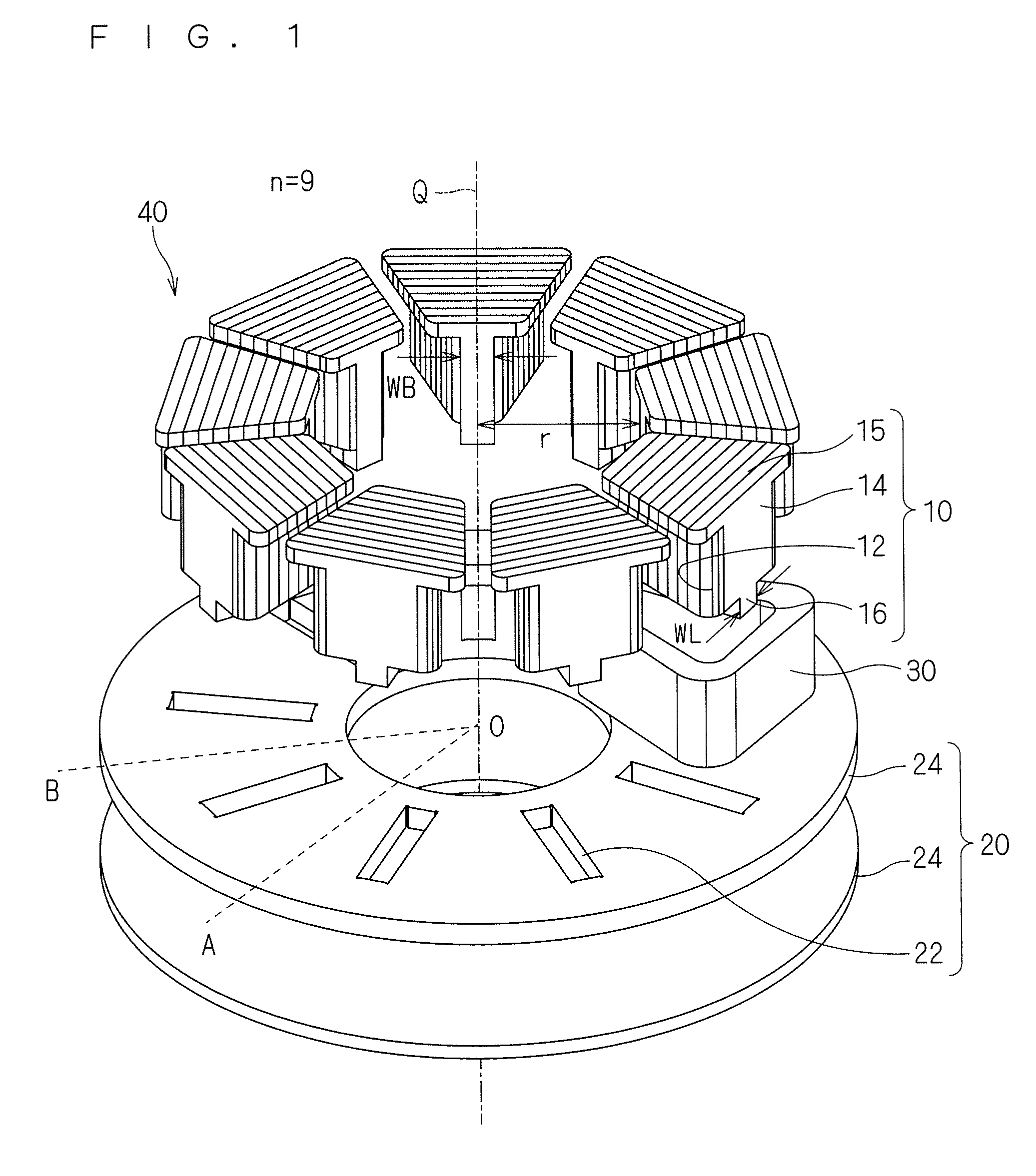
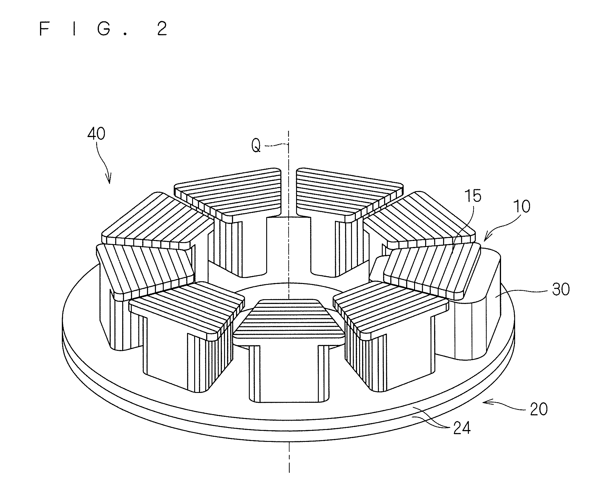
[0088]FIG. 1 is an exploded perspective view of an armature 40 according to a first embodiment of the present invention, which shows the armature 40 disassembled in a direction along a rotation axis Q. FIG. 2 is an assembly view of the armature 40. As shown in FIG. 1, the armature 40 includes armature cores 10, a yoke 20 and armature coils 30, which is applied to, for example, an axial gap motor (not shown). Note that unless particularly noted in the present application, the armature coil refers to a mode in which wires are wound as a whole, not to each wire constituting this. This holds true for the drawings as well. Leading lines in start and end of winding and wire connection thereof are also omitted in the drawings. FIG. 2 shows only one armature coil, and other armature coils are not shown for showing a form of the armature core.

[0089]The armature core 10 is formed by laminating a plurality of magnetic plates (corresponding to the “first magnetic plates” in Means to Solve the P...

second embodiment

Modification of Second Embodiment

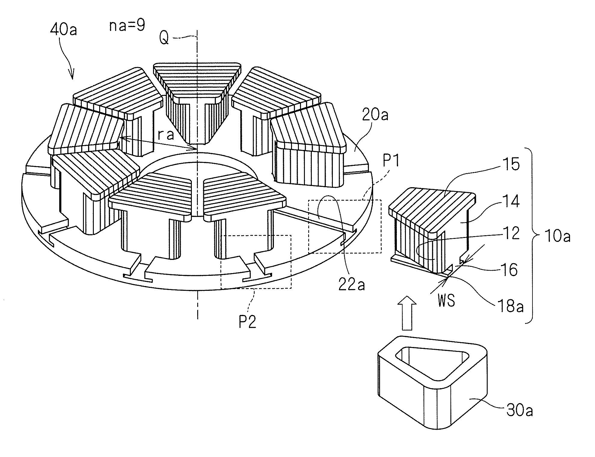
[0122]FIG. 7 is a partially enlarged view of the armature 40a according to a modification, which shows a region corresponding to a region P2 of the armature 40a shown in FIG. 4. As shown in FIG. 6, it is desired that the yoke 20a hold the end surface of the flanged portion 18a on the side opposite to the first rectangular solid portion 16 to hold the armature core 10a from the viewpoint of securing the strength of the armature 40a. However, in a case where the recessed portion 22a of the yoke 20a can hold the portion in the vicinity of the boundary between the prism portion 14 and the first rectangular solid portion 16 with a sufficient strength, as shown in FIG. 7, the end surface of the flanged portion 18a on the side opposite to the first rectangular solid portion 16 may be exposed.

Effects of Second Embodiment

[0123]As described above, the armature core 10a further includes the flanged portion 18a at the end portion of the first rectangular solid p...

third embodiment

[0126]Although the descriptions in the first and second embodiments above are given of the mode in which the width of the first rectangular solid portion 16 is equal to or smaller than the minimum value of the width of the prism portion 14, and in particular, the description in the second embodiment is given of the mode in which the flanged portion 18a is provided to the lower side of the first rectangular solid portion 16, the present invention is not limited thereto. The width of the first rectangular solid portion 16 may be larger than the minimum value of the width of the prism portion 14. Description is given here, as a third embodiment of the present invention, of a mode in which a width of a first rectangular solid portion 16c is equal to or larger than the maximum value of the width of the prism portion 14, with reference to the drawings.

[0127]FIG. 8 is an exploded perspective view of an armature 40c according to the third embodiment of the present invention, which shows the...


PUM


Abstract

An armature core is formed by laminating a plurality of first magnetic plates along a lamination direction. The armature core includes a prism portion and a first rectangular solid portion. The prism portion has a length measured in a first direction perpendicular to the lamination direction and a height measured in a second direction perpendicular to the lamination direction and the first direction. The length of the prism portion gradually increases along the lamination direction in at least part of the prism portion. The first rectangular solid portion is adjacent to the prism portion in the second direction. The first rectangular solid portion has a uniform length measured along the first direction. Preferably, a plurality of the armature cores are mounted on a yoke and have armature windings wound to form an armature of a rotary electric machine of a compressor.

Description

CROSS-REFERENCE TO RELATED APPLICATIONS[0001]This national phase application claims priority to Japanese Patent Application Nos. 2007-324859 filed on Dec. 17, 2007, and 2008-187545, filed on Jul. 18, 2008. The entire disclosures of Japanese Patent Application Nos. 2007-324859 and 2008-187545 are hereby incorporated herein by reference.TECHNICAL FIELD[0002]The present invention relates to an armature core and an armature, and particularly, is applicable to an axial gap rotary electric machine.BACKGROUND ART[0003]A rotary electric machine includes an armature and a field element. In particular, in an axial gap rotary electric machine, an armature and a field element are disposed so as to be opposed to each other along a rotation axis, through an air gap extending along a surface perpendicular to the rotation axis. The armature includes a yoke, teeth provided to the yoke, and a coil that is wound with the teeth being a core. The field element is rotated by a rotating magnetic field gen...

Claims


Application Information

Patent Timeline
IPC IPC(8): H02K1/06
CPCF04C23/008F04C23/02F04C29/0085H02K1/148F04C2240/803F04C2240/808F04C2240/40H02K21/24
Inventor ASANO, YOSHINARIYASUMOTO, RYUUJIKIFUJI, NOBUYUKI
Owner DAIKIN IND LTD
Why Eureka
Try Eureka