Electronically commutated motor

a technology of electric commutation and motor, applied in the direction of electronic commutators, dynamo-electric converter control, instruments, etc., can solve problems such as perceptible disruptions, and achieve the effects of reducing fluctuations in the average current consumed, improving customer utilization, and improving the effect of line-conducting emissions

Inactive Publication Date: 2010-10-14
EBM PAPST ST GEORGEN & -
View PDF10 Cites 10 Cited by
  • Summary
  • Abstract
  • Description
  • Claims
  • Application Information

AI Technical Summary

Benefits of technology

[0005]This object is achieved by a method which employs several controllers to smooth fluctuations in motor current by adjustment of the duty ratio of a Pulse Width Modulation (PWM) driving signal for the power stage. Such a method and an electric motor of this kind decrease fluctuations in the average current consumed by the power stage. This also has a positive effect on the line-conducted emissions. Fewer current peaks occur because of the current controller, and as a result the power supply section can be better utilized by the customer.

Problems solved by technology

In the telecommunications sector in particular, the line-conducted emissions emitted from a fan can result in disruptions that are perceptible, for example, as troublesome noise during telephone calls.

Method used


Image

  • Electronically commutated motor
  • Electronically commutated motor
  • Electronically commutated motor

Examples


Embodiment Construction

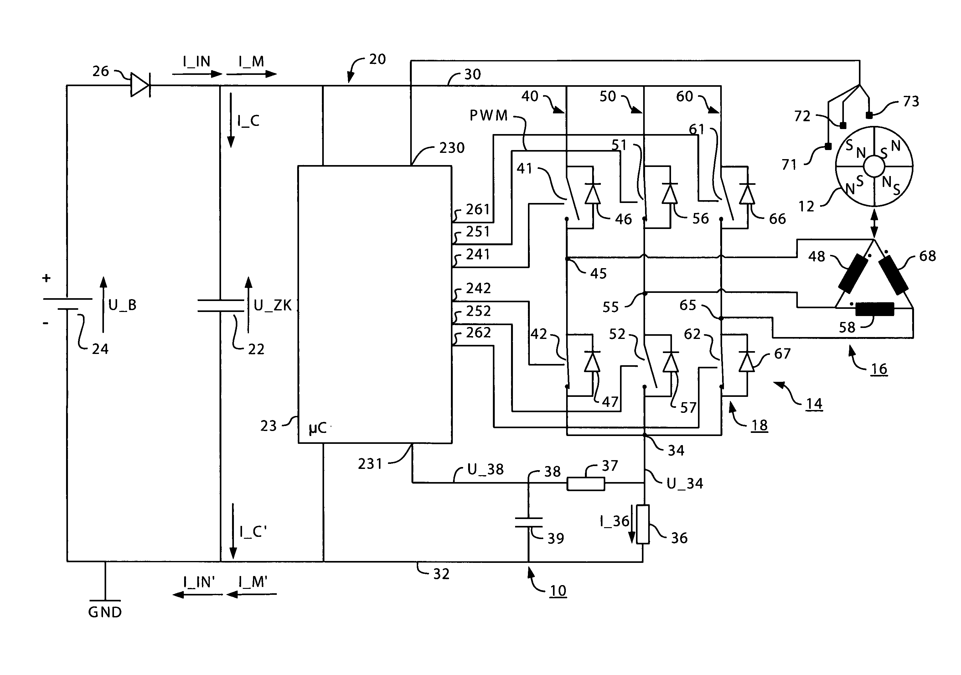
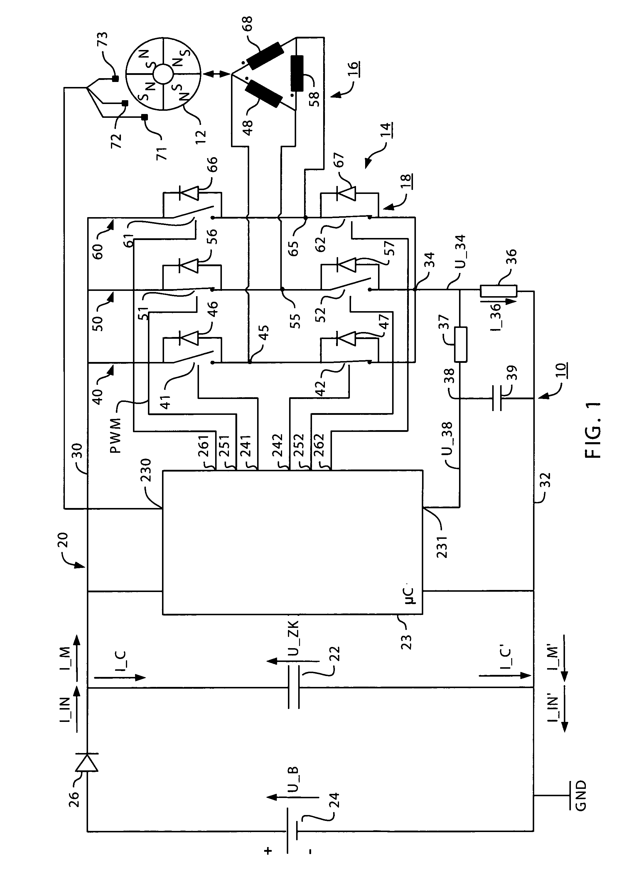
[0032]FIG. 1 shows an electric motor 10 having a rotor 12 and a stator 14, which comprises a winding arrangement 16 having three strands 48, 58, 68, and a power stage 18. Power stage 18 is connected, via an upper lead 30 and a lower lead 32 (GND), to a DC link circuit 20 having a link circuit capacitor 22.

[0033]A link circuit voltage U_ZK is present at link circuit capacitor 22, and the latter is connected, via an optional polarity protection diode 26, to a DC voltage source 24 having a voltage U_B.

[0034]A microprocessor or microcontroller, hereinafter called microcontroller μC 23, is likewise connected to DC link circuit 20, and serves to control motor 10.

[0035]Power stage 18 serves for current flow through winding arrangement 16, and has three bridge arms 40, 50, 60 having three upper switches 41, 51, 61 that connect upper lead 30 to three terminal nodes 45, 55, 65 for winding arrangement 16, and having three lower switches 42, 52, 62 that connect the three terminal nodes 45, 55, ...


PUM


Abstract

The invention relates to a method for operating an electronically commutated motor (10) that comprises a rotor (12), a stator (14) having a multi-strand winding arrangement (16) for whose energization a power stage (18) is provided, a first lead (30) and a second lead (32) for connecting the power stage (18) to a voltage source (24), and a first controller. A first signal (U_34; U_38) is sensed, which signal characterizes a current (I_IN; I_IN′; I_M; I_M′) flowing through at least one of the leads (30; 32); the first controller generates at least one clocked signal (PWM) and outputs it to the power stage (18) in order to influence the first value, permitted current. The invention also relates to a corresponding motor (10).

Description

CROSS-REFERENCE TO RELATED APPLICATIONS[0001]The present application is a section 371 of PCT / EP08 / 09797, filed 20 Nov. 2008, which in turn claims priority from our German application DE 10 2007 063 259.4, filed 18 Dec. 2007, the entire content of which is hereby incorporated by reference.FIELD OF THE INVENTION[0002]The invention relates to an electronically commutated motor, in particular for driving a fan.BACKGROUND[0003]In the telecommunications sector in particular, the line-conducted emissions emitted from a fan can result in disruptions that are perceptible, for example, as troublesome noise during telephone calls. The telecommunications sector therefore requires fans having a low level of low-frequency line-conducted emissions. This is advantageous for standard motors as well.SUMMARY OF THE INVENTION[0004]An object is therefore to make available a novel low-emission electronically commutated motor (ECM).[0005]This object is achieved by a method which employs several controller...

Claims


Application Information

Patent Timeline
Patent Type & Authority Applications(United States)
IPC IPC(8): H02P7/00
CPCH02P6/08H02P6/18
Inventor HOGG, GERALDKARWATH, ARNO
Owner EBM PAPST ST GEORGEN & -
Why Eureka
Try Eureka