Charged/Discharged Power control for a Capacitor Type Energy Storage Device

a power control and capacitor technology, applied in the direction of secondary cell servicing/maintenance, machines/engines, greenhouse gas reduction, etc., can solve the problems of increasing maintenance costs, difficulty in accurately detecting and figuring out the charge level and increasing the cost of the energy storage device. achieve the effect of preventing overcharge and overdischarge of lead batteries, reducing maintenance costs, and increasing the capacity of lead batteries

Inactive Publication Date: 2010-10-14
NISSAN DIESEL MOTOR CO
View PDF7 Cites 24 Cited by
  • Summary
  • Abstract
  • Description
  • Claims
  • Application Information

AI Technical Summary

Benefits of technology

[0006]A solution to prevent overcharge and overdischarge of the lead batteries is to increase the capacity of the lead batteries and thus allowing a margin in charge level control, but this method raises the cost of the energy storage device.
[0007]In addition, keeping the charge level of the energy storage device at a proper level necessitates frequent maintenance of the batteries, with the result that the maintenance cost increases.
[0015]It is therefore an object of this invention to efficiently control an energy storage device using a capacitor.

Problems solved by technology

When lead batteries are used as the energy storage device, inherent properties of the lead batteries make it difficult to detect and figure out the charge level of the energy storage device accurately.
A solution to prevent overcharge and overdischarge of the lead batteries is to increase the capacity of the lead batteries and thus allowing a margin in charge level control, but this method raises the cost of the energy storage device.
In addition, keeping the charge level of the energy storage device at a proper level necessitates frequent maintenance of the batteries, with the result that the maintenance cost increases.
Another problem is that degradation of some of unit cells is unavoidable despite maintenance, and that replacing degraded unit cells elevates the life cycle cost.

Method used


Image

  • Charged/Discharged Power control for a Capacitor Type Energy Storage Device
  • Charged/Discharged Power control for a Capacitor Type Energy Storage Device
  • Charged/Discharged Power control for a Capacitor Type Energy Storage Device

Examples


second embodiment

[0070]Referring to FIGS. 6-8, this invention will be described.

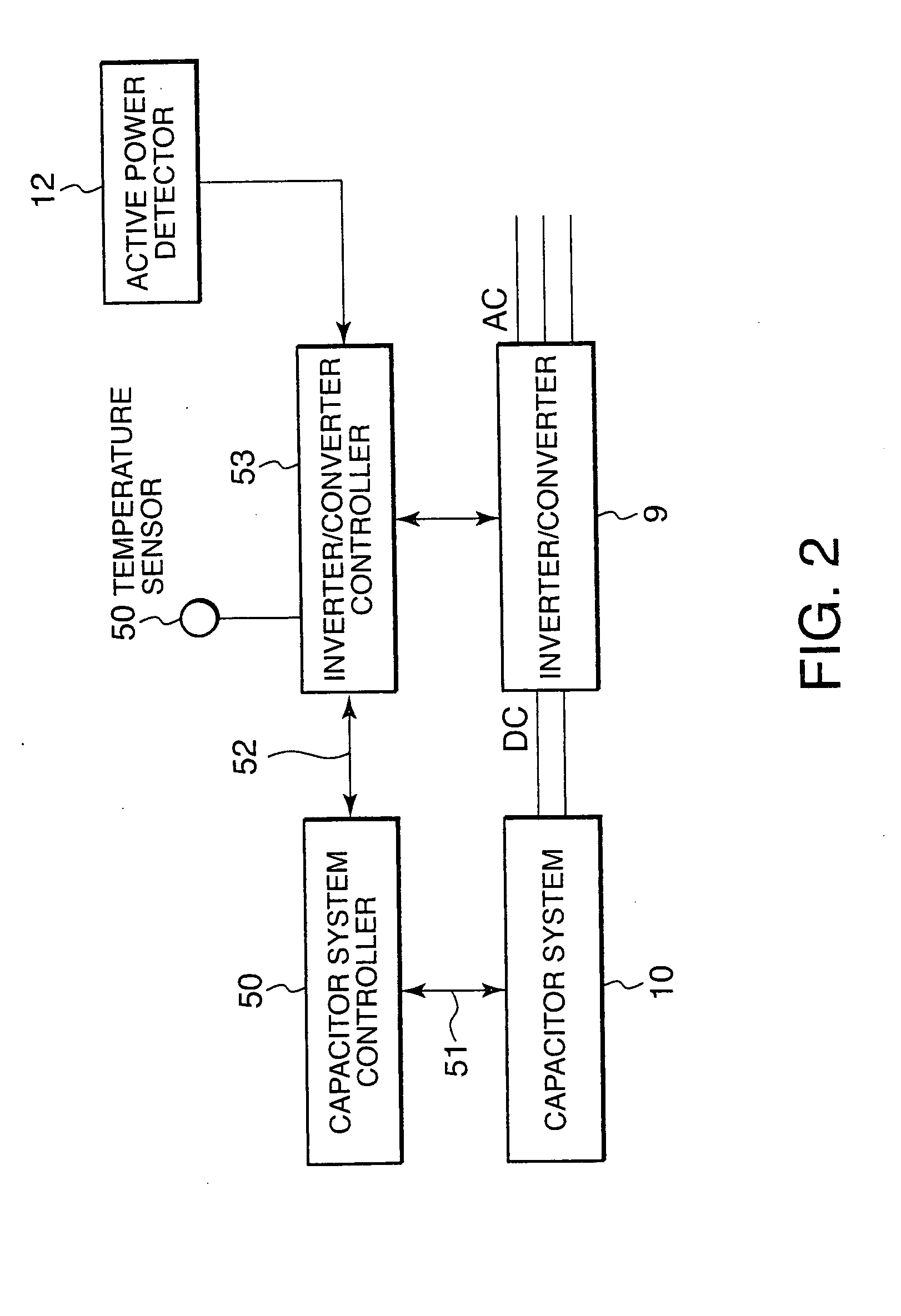
[0071]In this embodiment, the charged / discharged power is controlled with the use of limit values with respect to the temperature of the capacitor system 10 instead of the use of limit values with respect to the SOC. For this purpose, a temperature sensor 54 shown in FIG. 2 for detecting a temperature Tc (° C.) of the capacitor system 10 is connected to the inverter / converter controller 53.

[0072]FIG. 6 shows that the upper limit to the temperature of the capacitor system 10 is T2 (° C.), and a value lower than the upper limit T2 is set as a threshold T1 (° C.) for output power limitation. As in FIG. 3, above a point zero on the axis of ordinate, a state in which the capacitor system 10 is receiving a charge input power, in other words, a charge state is indicated by a positive value, whereas a negative value indicates a state in which the capacitor system 10 is outputting a discharge output power, in other words, a disch...

third embodiment

[0100]Referring to FIGS. 9-11, this invention will be described.

[0101]The first and second embodiments make the energy storage device 5 which has the capacitor system 10 free of maintenance and prolong the lifetime of the energy storage device 5 by executing charge input power limitation control and discharge output power limitation control.

[0102]On the other hand, the power stabilizing performance of the energy storage device 5 can be improved by efficiently utilizing the storage capacity of the capacitor system 10 and thus increasing the charge input power or discharge output power of the capacitor system 10.

[0103]The third embodiment relates to bias control of the energy storage device 5 to raise a mean SOC in order to fully utilize the storage capacity of the capacitor system 10.

first embodiment

[0104]FIG. 9 shows the relation between a running time of the capacitor system 10 and the SOC of the capacitor system 10 without bias control. As shown in the figure, the SOC lowers as the running time becomes longer, and the SOC fluctuates around 20%. A cause of this is a great power loss in charging resulting from a loss in charging the capacitor system 10 and a loss in making an input power to and output power from the inverter / converter 9. When only 20% of the storage capacity of the capacitor system 10 is used as in the case of this example, the SOC frequently reaches its lower limit L2 described in the first embodiment and the probability of the discharge output power being limited becomes accordingly higher. As a result, not enough effect of stabilization control is obtained.

[0105]In this embodiment, a given bias output (kW) is added to or subtracted from a charge input power and a discharge output power that are required for power stabilization so that the SOC of the capacit...


PUM

PropertyMeasurementUnit
poweraaaaaaaaaa
discharge output poweraaaaaaaaaa
output poweraaaaaaaaaa

Abstract

A charge / discharge of a capacitor system (10) with stacked electric double layer capacitors is regulated by an inverter / converter (9) for stabilizing an output power of a wind power generator (1). The inverter / converter controller (53) controls the inverter / converter (9) such that, when the state of charge (SOC) of the capacitor system (10) exceeds an upper threshold (H1), which is smaller than an upper limit (H2), the charged power of the capacitor system (10) gradually decreases according to an excess amount. The inverter / converter controller (53) also controls the inverter / converter (9) such that, when the state of charge (SOC) is below a lower threshold (L1) which is higher than a lower limit (L2), the discharged power of the capacitor system (10) gradually decreases according to a short amount, thereby preventing overcharging and overdischarging of the capacitor system (10).

Description

FIELD OF THE INVENTION[0001]This invention relates to a charged / discharged power control for an energy storage device using capacitors.BACKGROUND OF THE INVENTION[0002]JP 2002-101557 A published by Japan Patent Office in 2002 discloses an energy storage device to stabilize the output power of a wind power generation system.[0003]In this system, an objective level is set for the output power of a wind power generator and, when the output power of the generator exceeds the objective level, the energy storage device is charged with the excess power whereas the energy storage device discharges power to compensate for a shortage when the output power of the generator is lower than the objective level.[0004]Overcharge and overdischarge of the energy storage device has to be avoided in order to ensure the safety and durability of the energy storage device. It is also necessary to keep the charge level of the energy storage device at a proper level so that the energy storage device can prov...

Claims


Application Information

Patent Timeline
Patent Type & Authority Applications(United States)
IPC IPC(8): H01M10/44
CPCF03D9/003H01M10/06Y02E70/30Y02E10/72Y02E10/766H02J3/32F03D9/255Y02E10/76Y02E60/10F03D9/11
Inventor SASAKI, MASAKAZUSAITOU, TETSUO
Owner NISSAN DIESEL MOTOR CO
Why Eureka
Try Eureka