Profilometer

a technology of profilometer and light source, applied in the field of profilometer, can solve the problems of difficult analytically to obtain the precise distribution of light source li(p, , ) and objects whose reflectance properties are not uniform, and achieve the effect of satisfying accuracy

Inactive Publication Date: 2010-10-14
ORMON CORP
View PDF3 Cites 25 Cited by
  • Summary
  • Abstract
  • Description
  • Claims
  • Application Information

AI Technical Summary

Benefits of technology

[0022]According to one or more embodiments of the present invention, the normal information (XYZ component of unit vector, or zenith angle component and azimuth angle component) can be calculated with satisfactory accuracy even on a measuring target in which the reflectance property is not uniform, or in which the reflectance property is uniform but which reflectance property itself differs from the reference object.

Problems solved by technology

In the color highlight method using color features, an object whose reflectance property is not uniform cannot be measured.
However, it is analytically difficult to obtain the light source distribution Li(p, θ, φ) that precisely satisfies the right side of the equation (1)=the right side of the equation (2).

Method used


Image

  • Profilometer
  • Profilometer
  • Profilometer

Examples


first embodiment

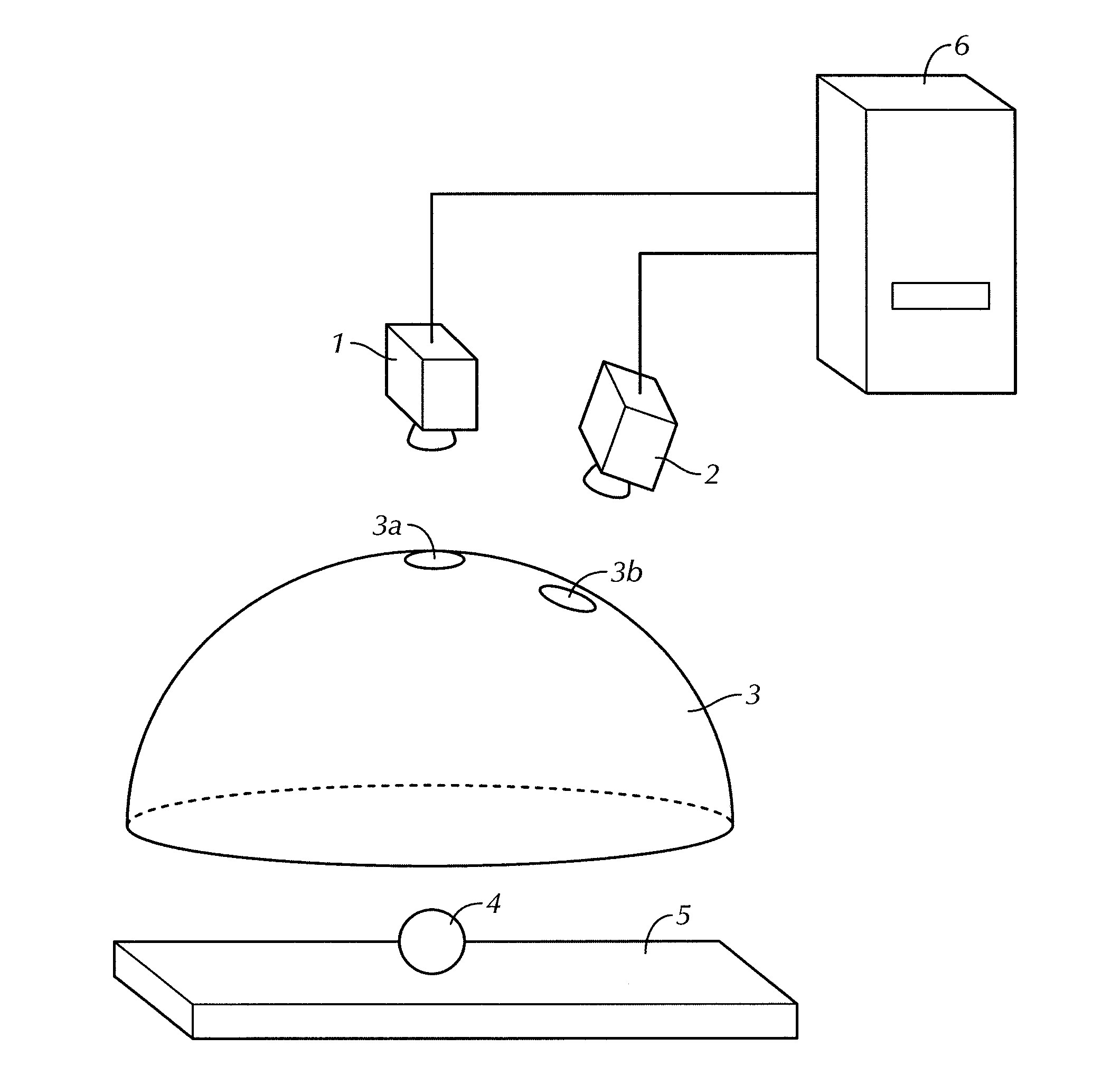
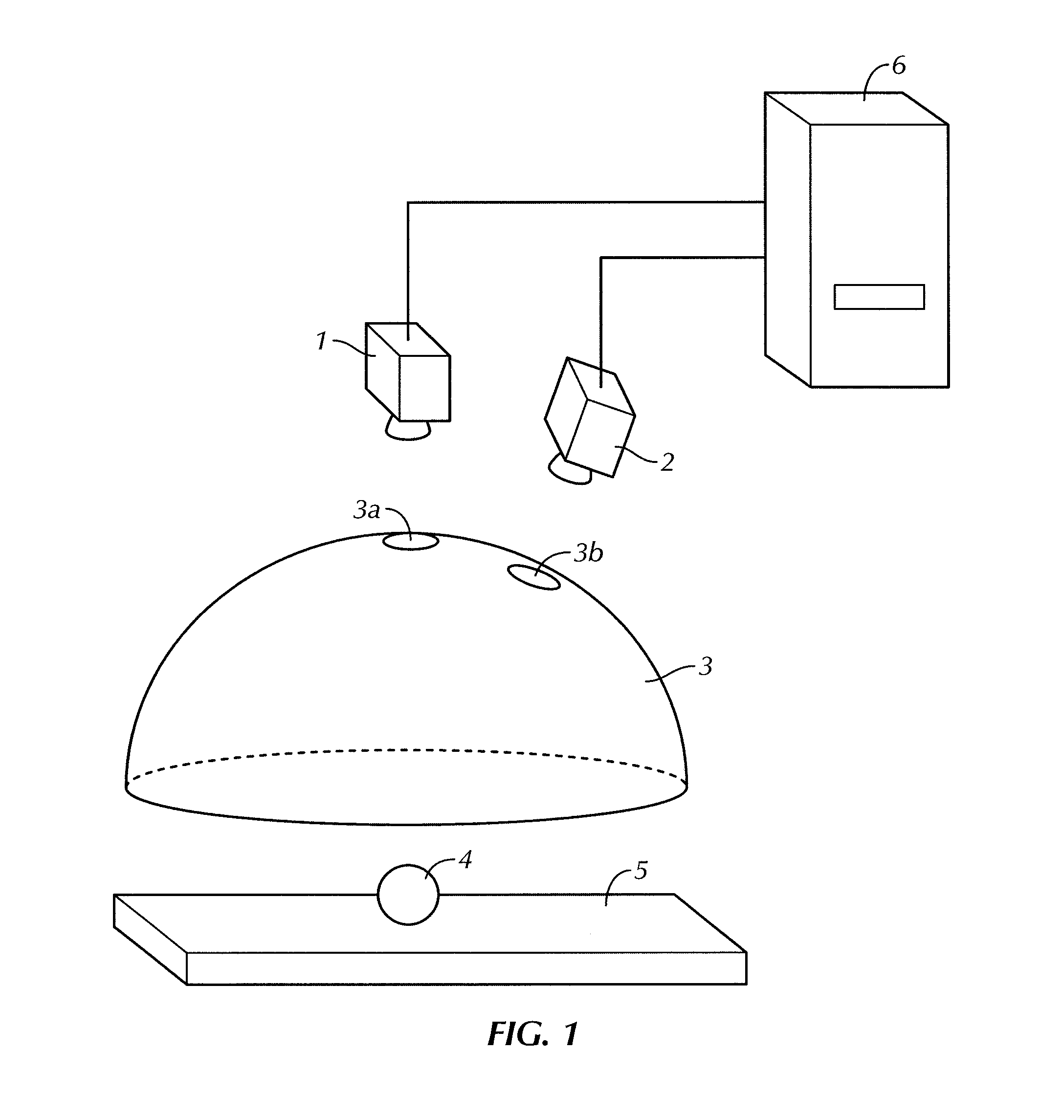
[0045]A profilometer (normal measurement device) according to a first embodiment is used as one part of a three-dimensional measurement device for performing a three-dimensional measurement of a mirror surface object. As shown in FIG. 18, the three-dimensional measurement (triangulation) is a technique of examining the correspondence relationship of pixels from images photographed with a plurality of cameras of different imaging angle, and calculating a parallax to measure the distance. Normally, the corresponding pixel is examined by calculating the similarity with the luminance value as a feature quantity when examining the corresponding pixel.

[0046]If the measuring target is a mirror surface object, the luminance value photographed in the image does not represent the feature quantity of the object surface itself, but is determined by the reflection of the surrounding object. Therefore, when the mirror surface object is photographed with two cameras, as shown in FIG. 19, the posit...

second embodiment

[0097]In the first embodiment, a pattern in which the light emission intensity linearly changes with respect to the angle in the longitude direction as shown in FIG. 5A is used as an approximation solution of a lighting pattern with which the spectral characteristics in the regular reflection direction can always be detected in the photographed image even if the reflectance property changes. In the present embodiment, a pattern in which the light emission intensity linearly changes with respect to a latitude direction as shown in FIG. 15 is adopted. Such lighting pattern is also one approximation solution, and the influence of diffusion light can be substantially canceled out to enable the detection of the regular reflection light.

third embodiment

[0098]In a profilometer according to the third embodiment, a lighting device having a shape different from the first and the second embodiments is used. As shown in FIG. 16, a flat plate-shaped lighting device 11 is used in the present embodiment. In the present embodiment as well, the spectral distribution of the light emission at each position in the light emission region is differed at all positions. Specifically, similar to the first embodiment, when determining light emission by synthesis of light components of three colors of red light (R), green light (G), and blue light (B), each color is changed with respect to different directions as shown in FIG. 17. Here, the light emission intensity of R becomes larger towards the rightward direction, the light emission intensity of G becomes larger towards the leftward direction, and the light emission intensity of B becomes larger towards upward direction. The proportion of change in the light emission intensity is linear with respect...


PUM


Abstract

A profilometer for measuring a surface profile of a measuring target has a lighting device for irradiating the measuring target with light, an imaging device for imaging a reflected light from the measuring target, and a normal calculation section for calculating a normal direction of a surface at each position of the measuring target from an imaged image. The lighting device has a light emission region of a predetermined extent. A radiance of center of gravity of a light source distribution of a point symmetric region coincides with a radiance of the center of the point symmetric region in an arbitrary point symmetric region of the light emission region.

Description

BACKGROUND OF THE INVENTION[0001]1. Technical Field[0002]The present invention relates to a technique of measuring the profile of a surface or surface normals of a measuring object.[0003]2. Related Art[0004]A technique of using color information and a technique of using luminance information are conventionally known as a technique of measuring a normal profile of a measuring target.[0005]A color highlight method is known as a technique of measuring the normal profile using the color information. As shown in FIGS. 20A and 20B, the color highlight method includes arranging red, blue, and green ring lightings in a dome, and irradiating the measuring target with each color. The direction of a normal line (only zenith angle component) of the surface to be measured is distinguished in three ways by analyzing the color of reflected light from the measuring target to calculate the surface profile. As a modification of the color highlight method, a technique (refer to, for example, Japanese ...

Claims


Application Information

Patent Timeline
Patent Type & Authority Applications(United States)
IPC IPC(8): G01C3/08
CPCG01B11/245G01B11/24
Inventor OHNISHI, YASUHIROKIMACHI, MASATOSHISUWA, MASAKINAYAR, SHREE
Owner ORMON CORP
Why Eureka
Try Eureka