Installable assembly having an expandable outer member and a fastener with a mandrel

a technology of installable assembly and mandrel, which is applied in the direction of fastening means, rivets, dowels, etc., can solve the problems of unfavorable electrical performance, unfavorable electrical performance, and unfavorable electrical performance of joints, so as to reduce, limit, or substantially eliminate the and achieve no appreciable damage to the workpiece

Active Publication Date: 2010-10-14
FATIGUE TECH
View PDF29 Cites 41 Cited by
  • Summary
  • Abstract
  • Description
  • Claims
  • Application Information

AI Technical Summary

Benefits of technology

[0007]At least some embodiments disclosed herein involve installing an expandable outer member within an opening in a workpiece and pulling a fastener into the outer member in a single operation. The outer member serves as a protective liner and is controllably expanded to minimize, limit, or substantially eliminate damage to the workpiece. The outer member enhances performance and provides the ability to remove the fastener with no appreciable damage to the workpiece. The outer member, in some embodiments, remains secured to the workpiec...

Problems solved by technology

Unfortunately, these types of joints are susceptible to fatigue damage and have undesired electrical properties.
Contaminates (e.g., moisture, chemicals, debris, and other foreign substances) can become lodged between faying surfaces of joints and between the workpiece and bolt resulting in impaired electrical performance, increased wear, and increased corrosion.
Cyclic loading can lead to fatigue problems.
Conventional fastener assemblies may allow workpiece components to move relative to one another, which may result in fretting, excessive stresses at the interfaces of the hole and the bolt, vibrations, and the like.
In aerospace applications, conventional joints may thus have a relatively short in-service life.
Additionally, conventional fastener assemblies may be prone to electrical arcing or spark formation if the electrical current flows through the fastener assembly, for example, due to a lightning strike.
Aircraft are often made of l...

Method used


Image

  • Installable assembly having an expandable outer member and a fastener with a mandrel
  • Installable assembly having an expandable outer member and a fastener with a mandrel
  • Installable assembly having an expandable outer member and a fastener with a mandrel

Examples


Embodiment Construction

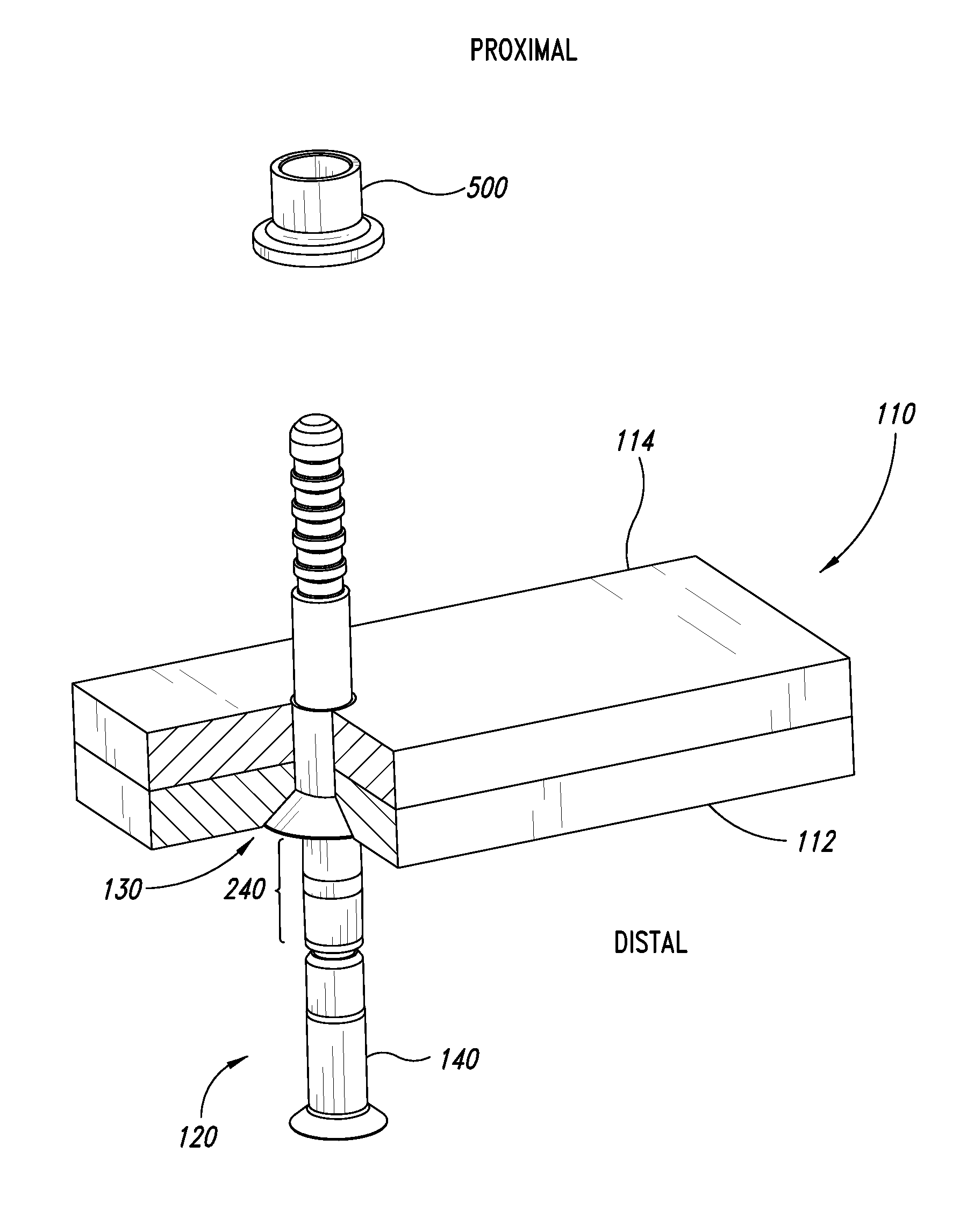
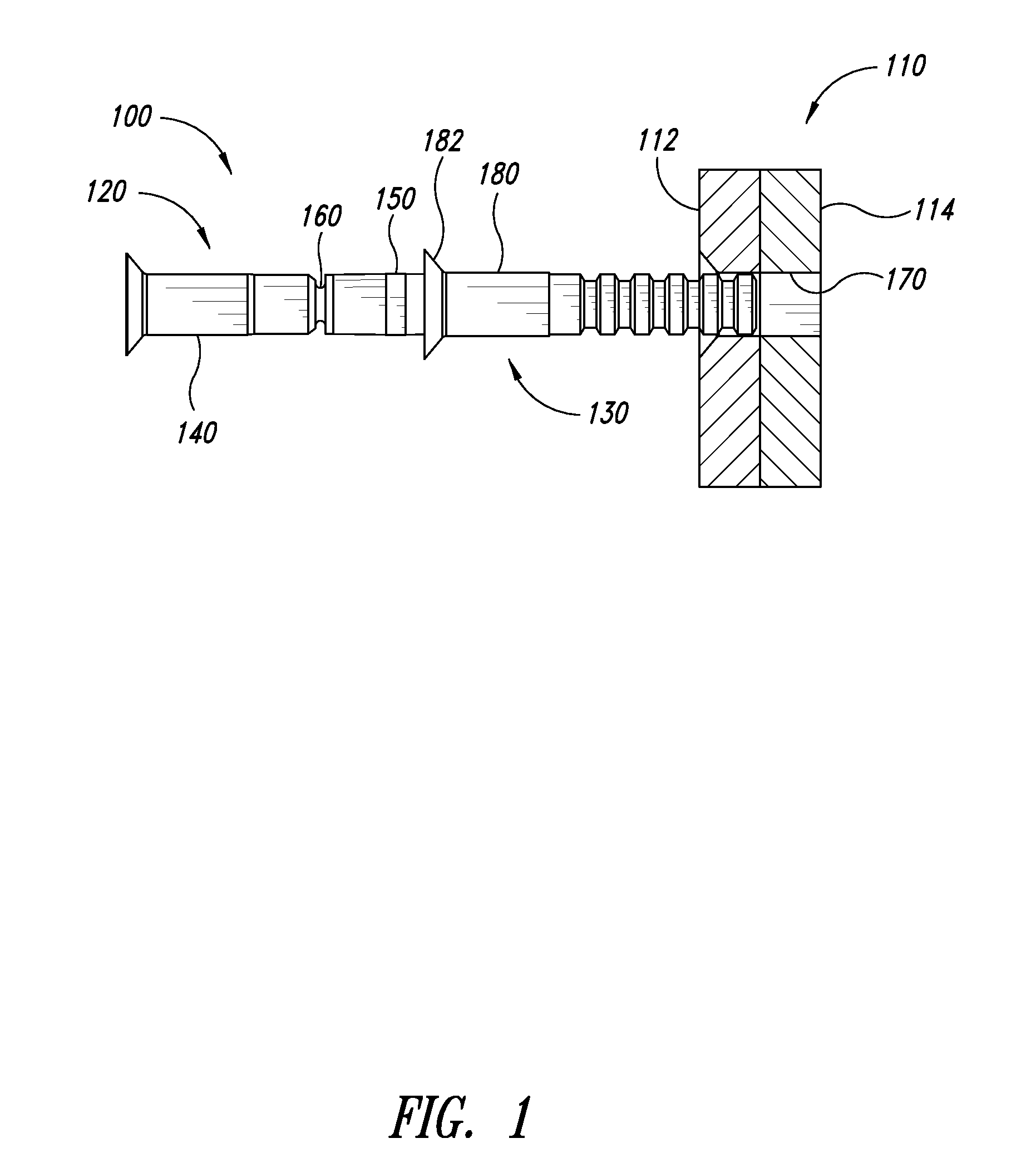
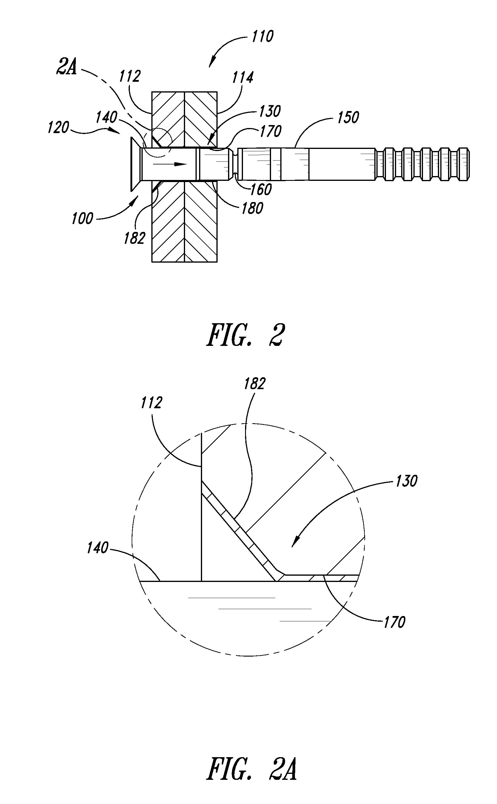
[0047]In the following description, certain specific details are set forth in order to provide a thorough understanding of various aspects of representative embodiments. One skilled in the art, however, will understand that the embodiments may be practiced without these details. The assemblies, installation apparatuses, and processes disclosed herein can be used to couple together workpieces and, in some embodiments, may improve in-service performance of these workpieces, such as electrical performance, mechanical performance, fatigue performance, lightning strike performance, or the like. The assemblies can be installed at a wide range of locations. The phrase “expandable assembly” refers to an assembly both in a pre-expanded state and an expanded state, unless the context dictates otherwise.

[0048]Unless the context requires otherwise, throughout the specification and claims which follow, the word “comprise” and variations thereof, such as, “comprises” and “comprising” are to be co...


PUM


Abstract

A fastener assembly is installable in an opening of a workpiece and includes an outer member and a fastener. The fastener is movable through a passageway of the outer member. The fastener includes a mandrel and a stem. The mandrel is dimensioned to radially expand the outer member. The stem has an expansion portion and a propping portion. The expansion portion radially expands the outer member after the outer member has been expanded by the mandrel. The propping portion keeps the expanded outer member in an installed expanded configuration. The outer member and fastener are installed in a single operation to reduce installation time.

Description

CROSS-REFERENCE TO RELATED APPLICATION[0001]This application claims the benefit under 35 U.S.C. §119(e) of U.S. Provisional Patent Application No. 61 / 168,544 filed Apr. 10, 2009. This provisional application is incorporated herein by reference in its entirety.BACKGROUND[0002]1. Technical Field[0003]This disclosure generally relates to assemblies for installation in a workpiece. The assemblies include expandable outer members and fasteners.[0004]2. Description of the Related Art[0005]Fastener assemblies are often used to interconnect a plurality of workpieces, such as a stack of plates or other structural members. Some conventional fastener assemblies have a bolt and a collar that cooperate to apply a clamp-up force to a multi-component workpiece (e.g., overlapping panels). To form a joint, a hole is drilled through the multi-component workpiece. A bolt is then inserted through the hole such that an end of the bolt protrudes outwardly from the workpiece. The workpiece is clamped betw...

Claims


Application Information

Patent Timeline
IPC IPC(8): F16B19/10
CPCF16B4/004F16B19/05F16B5/04
Inventor WEHRMEISTER, MARKBAKKEN, DOUGWEISS, MARK
Owner FATIGUE TECH
Why Eureka
Try Eureka