Method for the laser welding of a composite material to a component, and laser-weldable composite material for such a method

Active Publication Date: 2010-10-14
ALANOD GMBH
View PDF3 Cites 9 Cited by
  • Summary
  • Abstract
  • Description
  • Claims
  • Application Information

AI Technical Summary

Benefits of technology

[0014]The present invention is based on the object of providing a method of the type described in the introduction for the laser welding of a composite material to a component and also a laser-weldable composite material of the type described in the introduction that is suitable for this method, wherein an increased efficiency of the welding process is intended to be achieved in conjunction with high functionality and in conjunction with producibility of the composite material involving the least possible outlay.

Problems solved by technology

Moreover, since a high temperature is intended to be generated for welding by the laser beam at the welding location, the use of highly reflective surfaces proves to be counterproductive with regard to the energy input brought about by the laser beam.
Such an orientation of the laser beam requires a very precise and therefore complex alignment and cannot be realized particularly when a plurality of closely adjacent cylindrical components having a relatively large diameter are intended to be welded to the planar component.
The metallic coating materials mentioned are in part expensive or the coating process also in part constitutes an increased outlay.

Method used


Image

  • Method for the laser welding of a composite material to a component, and laser-weldable composite material for such a method
  • Method for the laser welding of a composite material to a component, and laser-weldable composite material for such a method
  • Method for the laser welding of a composite material to a component, and laser-weldable composite material for such a method

Examples


Embodiment Construction

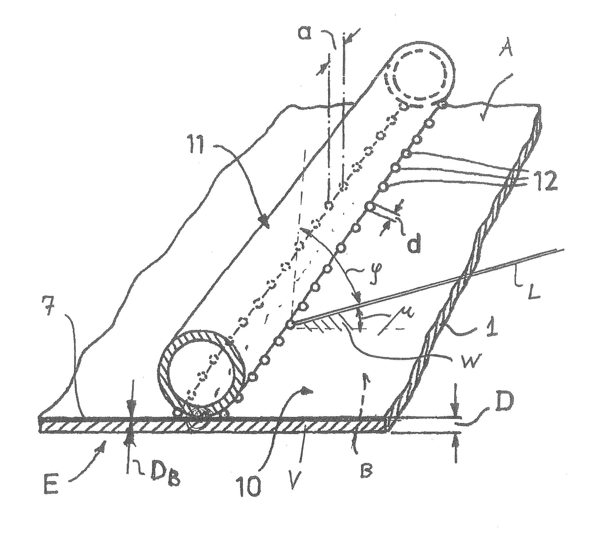
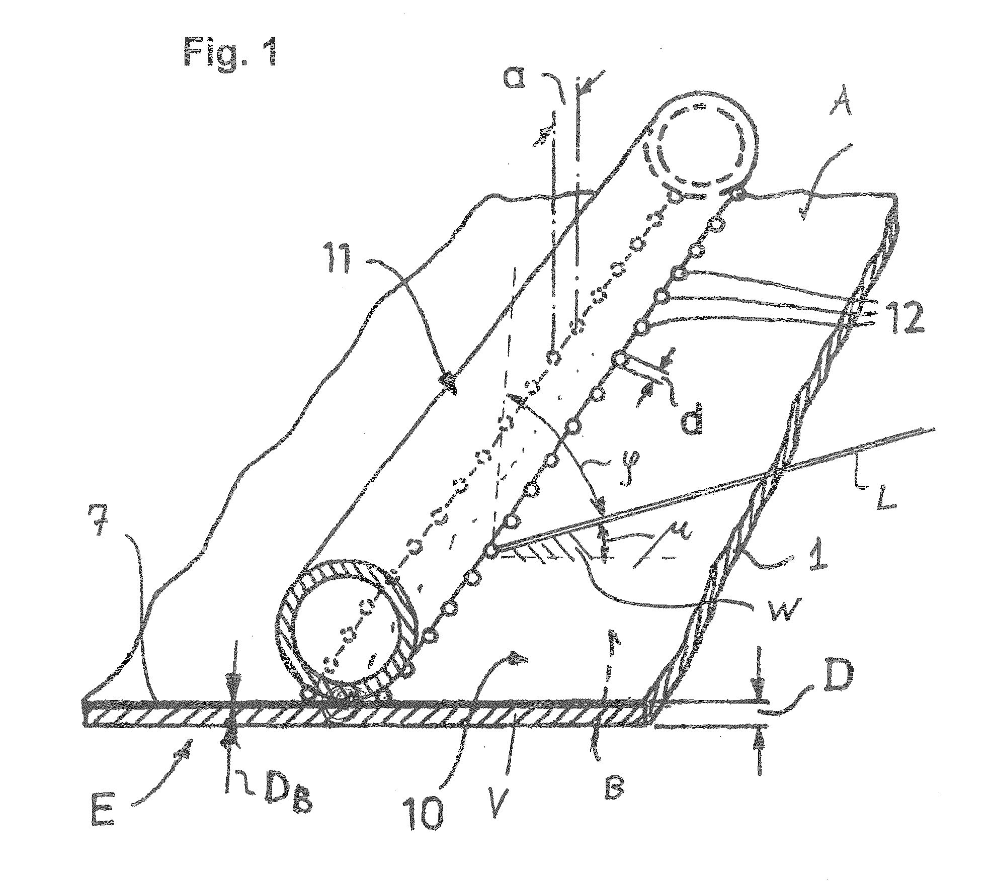
[0029]FIGS. 1 and 2 illustrate the overall construction of a solar collector element E that can be produced according to the method according to the invention and with the composite material V according to the invention. From the solar collector element E, the drawing in accordance with FIG. 1 schematically illustrates an absorber part 10 and a tube 11 for a heat-transfer liquid—as an example of a component to be welded to the composite material V according to the invention.

[0030]The absorber part 10 is composed of the composite material V according to the invention, having a substrate 1 composed of aluminum—as an example of a metal having high reflectivity to laser radiation. The substrate 1 has a first side A and a second side B. On the substrate 1, a multilayer system 3 comprising three layers 4, 5, 6 is situated above an interlayer 2 on the second side B—as shown in FIG. 6—, which multilayer system will be explained in even greater detail below. A dielectric coating 7 is situate...


PUM

PropertyMeasurementUnit
Fractionaaaaaaaaaa
Fractionaaaaaaaaaa
Fractionaaaaaaaaaa

Abstract

The invention relates to a method for the laser welding of a composite material (V) to a component (11) in particular for the production of a solar collector element (E), wherein the composite material (V) comprises a strip-shaped substrate (1) composed of a metal having high reflectivity to laser radiation, said substrate having a first side (A) and a second side (B), wherein a dielectric coating (7) is situated at least on the first side (A), and wherein, in order to produce a weld seam, a laser beam (L) is projected at an acute orientation angle (μ) at least onto the first side (A) of the substrate (1) provided with the dielectric coating (7). In order to improve the energy efficiency of the laser radiation used, it is proposed that the dielectric coating (7) has a thickness (DB) in the range of 140 nm to 210 nm and the laser beam (L) is radiated in at an orientation angle (μ), in particular in focused fashion, in such a way that the radiated-in energy of the laser beam (L) is absorbed to the extent of at least 15 percent.

Description

RELATED APPLICATIONS[0001]The present patent document claims the benefit of the filing date under 35 U.S.C.§119 of Provisional U.S. Patent Application Ser. No. 61 / 171,536, filed Apr. 22, 2009, and under 35 U.S.C.§119 of German Patent Application No. DE 102009016805.2 filed Apr. 9, 2009 which are hereby incorporated by reference.BACKGROUND OF THE INVENTION[0002]The present invention relates to a method for the laser welding of a composite material to a component in particular for the production of a solar collector element, wherein the composite material comprises a strip-shaped substrate composed of a metal having high reflectivity to laser radiation, said substrate having a first side and a second side, wherein a dielectric coating is situated at least on the first side, and wherein, in order to produce a continuous weld seam or discrete weld spots, a laser beam is projected at an acute orientation angle at least onto the first side of the substrate provided with the dielectric coa...

Claims


Application Information

Patent Timeline
IPC IPC(8): B32B15/04B23K26/00B32B15/20F24S10/70F24S10/75
CPCB23K26/26B23K2201/14B23K2203/18Y10T428/265F28F2275/067Y02E10/40F24J2/4652F24S70/30B23K2101/14B23K2101/34B23K2103/12B23K2103/172B23K2103/18
Inventor KUSTER, HARALDPEROS, DIMITRIOS
Owner ALANOD GMBH
Why Eureka
Try Eureka