Ignition device for a laser ignition system of an internal combustion engine

a laser ignition and internal combustion engine technology, which is applied in the ignition of combustion engines, machines/engines, engine ignition, etc., can solve the problems of redundancy of seals, failure of ignition lasers, and increased protection against loss of seal function

Inactive Publication Date: 2010-10-21
ROBERT BOSCH GMBH
View PDF5 Cites 16 Cited by
  • Summary
  • Abstract
  • Description
  • Claims
  • Application Information

AI Technical Summary

Benefits of technology

[0004]An object of the present invention is to provide an ignition laser in which the combustion chamber window and the housing are sealed in such a way that secure and reliable sealing of the combustion cham

Problems solved by technology

If the exhaust gases should enter the interior of the ignition laser, this would result in failure of the ignition l

Method used


Image

  • Ignition device for a laser ignition system of an internal combustion engine
  • Ignition device for a laser ignition system of an internal combustion engine
  • Ignition device for a laser ignition system of an internal combustion engine

Examples


Embodiment Construction

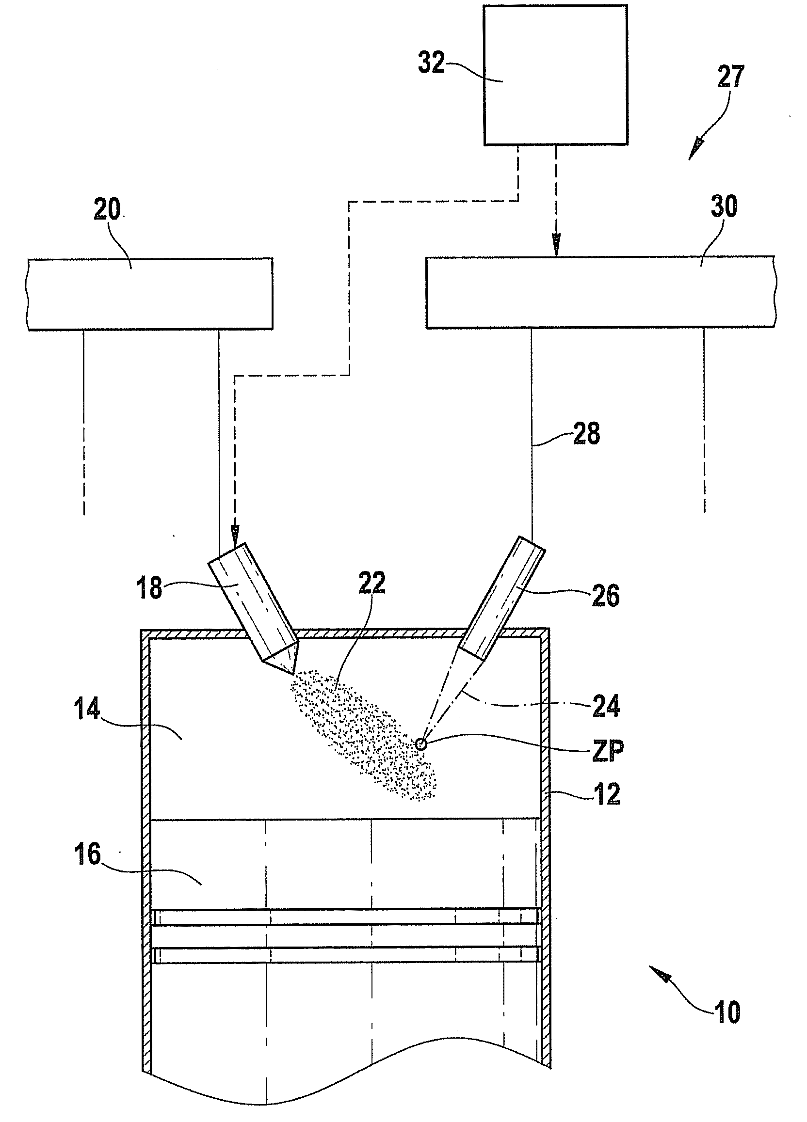
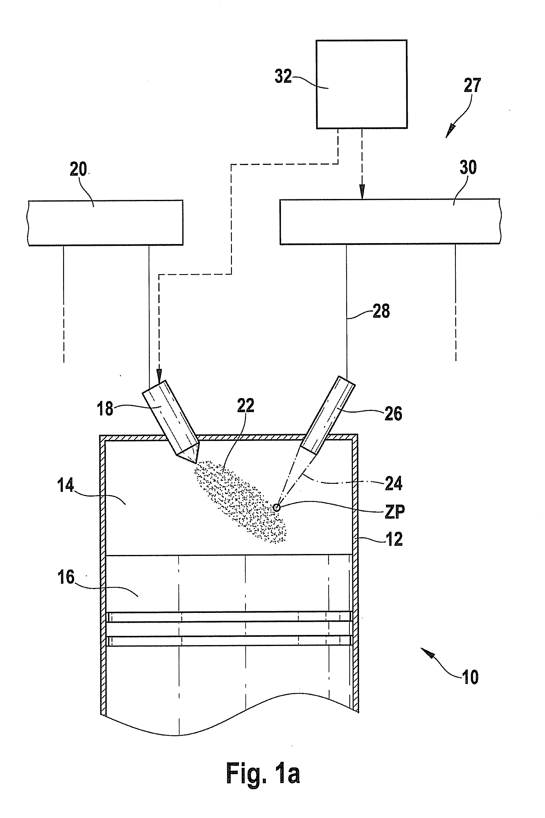
[0030]An internal combustion engine is collectively denoted by reference numeral 10 in FIG. 1a. The internal combustion engine may be used to drive a motor vehicle. Internal combustion engine 10 typically includes multiple cylinders, of which only one is denoted by reference numeral 12 in FIG. 1a. A combustion chamber 14 for cylinder 12 is delimited by a piston 16. Fuel passes directly into combustion chamber 14 via an injector 18, which is connected to a fuel pressure accumulator 20, also referred to as a rail. Alternatively, the fuel-air mixture may be formed outside combustion chamber 14, for example in the intake manifold.

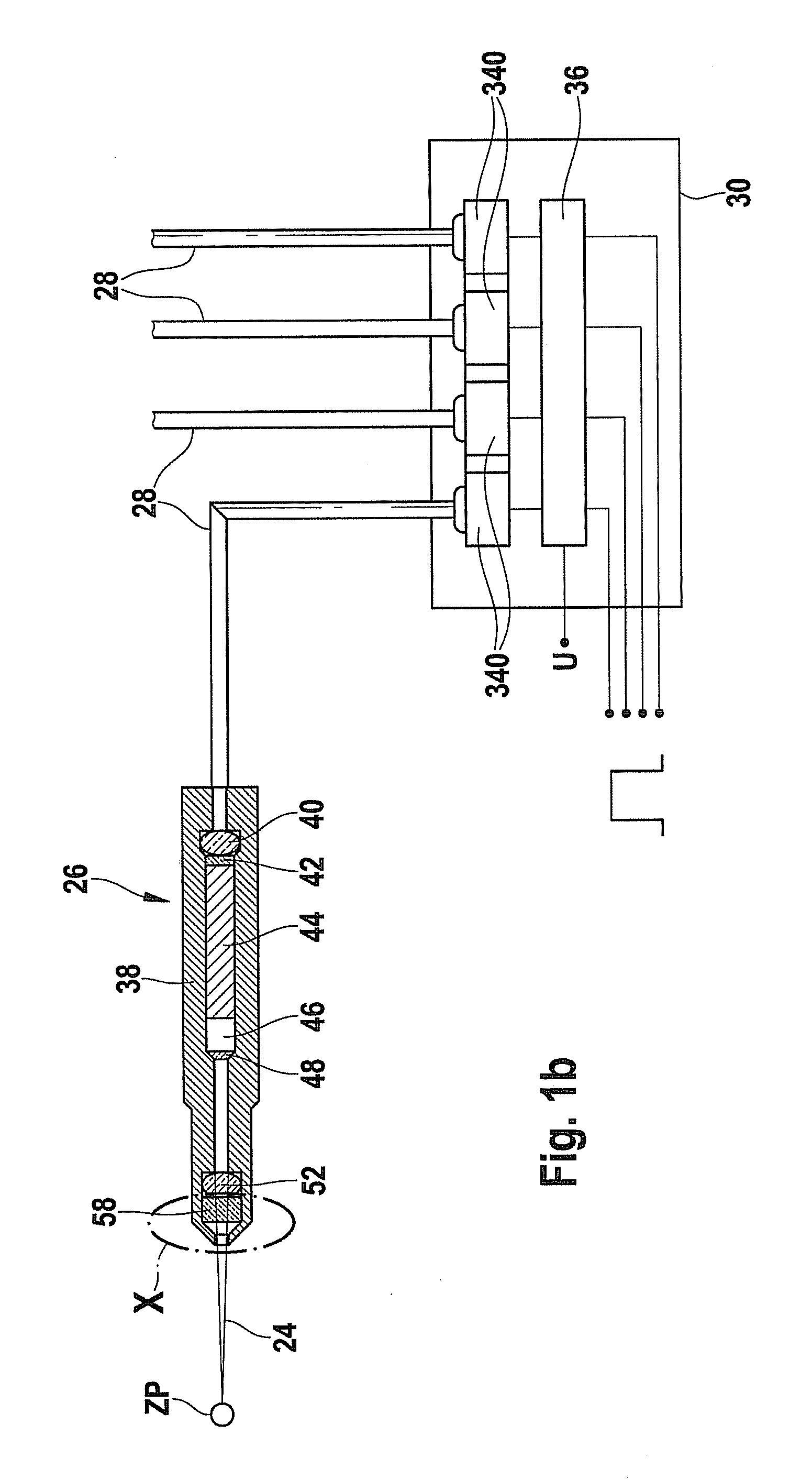
[0031]Fuel-air mixture 22 present in combustion chamber 14 is ignited using a laser pulse 24 which is emitted into combustion chamber 14 by use of an ignition device 27 which includes an ignition laser 26. For this purpose, laser unit 24 is fed via an optical fiber device 28, using a pumped light which is provided by a pumped light source 30. Pumped light sourc...


PUM


Abstract

An ignition laser for an internal combustion engine is provided, wherein the combustion chamber window is connected to a housing of the ignition laser in a gas-, pressure-, and temperature-resistant manner.

Description

BACKGROUND INFORMATION[0001]A so-called laser ignition system is described in PCT Application WO 2005 / 066488 A1. This laser ignition system includes an ignition laser which projects into the combustion chamber of an internal combustion engine. The ignition laser is optically pumped from a pumped light source using an optical fiber.[0002]At one end of the ignition laser facing the combustion chamber, a combustion chamber window is present which is transmissive for the laser beams generated in the ignition laser. This combustion chamber window is accommodated in a sealing manner in a housing of the ignition laser. Great demands are placed on the seal between the combustion chamber window and the housing due to the fact that surface temperatures of over 600° C. may occur at the combustion chamber window during operation of the internal combustion engine. In addition, there are intermittent pressure loads of greater than 250 bar. When an ignition laser is used to ignite a gas turbine, a...

Claims


Application Information

Patent Timeline
IPC IPC(8): F02P23/04
CPCF02P23/04
Inventor WEINROTTER, MARTINWOERNER, PASCALRAIMANN, JUERGEN
Owner ROBERT BOSCH GMBH
Why Eureka
Try Eureka