
Aluminum alloy clad sheet for heat exchangers and method of producing the same

a technology of aluminum alloy and heat exchanger, which is applied in the direction of manufacturing tools, soldering devices, light and heating equipment, etc., can solve the problems of difficult pressing of materials, low processing area, and eroded core materials of filler metals in low processing areas, and achieve excellent brazing.

Inactive Publication Date: 2010-10-21
SUMITOMO LIGHT METAL INDS LTD
View PDF4 Cites 16 Cited by
  • Summary
  • Abstract
  • Description
  • Claims
  • Application Information

AI Technical Summary

Benefits of technology

[0011]The present invention was conceived as a result of conducting tests and studies on the relationship between the composition of the outer-side cladding material, the brazability of the outer-side cladding material and the bare fin material, and the sacrificial anode properties of the outer-side cladding material in order to solve the above problems to obtain outer-side brazability and outer-side corrosion resistance. An object of the present invention is to provide an aluminum alloy clad sheet for heat exchangers that exhibits excellent brazability and outer-side corrosion resistance, and is suitably used as a member (particularly a tube material or a tank or header material) of an aluminum alloy heat exchanger that is produced by inert-gas brazing using a fluoride flux. Another object of the present invention is to provide a method of producing an aluminum alloy clad sheet for heat exchangers that is an H-temper material and exhibits elongation sufficient for hard working (e.g., press working).
[0030]The present invention thus provides an aluminum alloy clad sheet for heat exchangers that exhibits excellent brazability and outer-side corrosion resistance, and is used as a member of an aluminum alloy heat exchanger that is produced by inert-gas brazing using a fluoride flux. The present invention thus also provides a method of producing an aluminum alloy clad sheet for heat exchangers that is an H-temper material and exhibits elongation sufficient for hard working (e.g., pressing). The aluminum alloy clad sheet according to the present invention may be suitably used as a tube material or a tank or header material.

Problems solved by technology

However, when the material is clad with a filler metal, the filler metal erodes the core material in the low-processed area during brazing.
This phenomenon significantly occurs when using a thin material so that a sound brazed state may not be obtained.
However, since the material has an elongation of about 1 to 2%, it is difficult to press-work the material.
If the refrigerant tube is perforated at an early stage due to corrosion from the outer side, the refrigerant leaks so that the function of the heat exchanger is impaired.
In this case, the self-corrosion resistance of the fin material may decrease due to the filler metal that remains on the surface of the fin, or the production cost of the heat exchanger may increase since the production cost of the clad fin material is higher than that of the bare fin.
When applying a filler metal powder to the surface of the Al—Zn alloy, however, the production cost of the heat exchanger increases since the filler metal powder is expensive.
When using a sheet material that is clad with an Al—Si alloy filler metal that contains Zn, since the molten filler metal that contains Zn flows during brazing, the amount of Zn that remains on the outer side of the refrigerant tube after brazing is not sufficient to provide a sacrificial anode material, the refrigerant tube may not exhibit sufficient corrosion resistance, or the molten filler metal that contains Zn may flow to the joint and cause preferential corrosion of the joint.
When using the above method, however, a sufficient amount of liquid phase for bonding the bare fin material is not obtained if the amount of Si is inappropriate.
As a result, corrosion resistance decreases.

Method used


Image

  • Aluminum alloy clad sheet for heat exchangers and method of producing the same
  • Aluminum alloy clad sheet for heat exchangers and method of producing the same
  • Aluminum alloy clad sheet for heat exchangers and method of producing the same

Examples


examples

[0063]The present invention is described below by way of examples and comparative examples. Note that the following examples merely illustrate several aspects of the present invention. The present invention is not limited to the following examples.

(Test A)

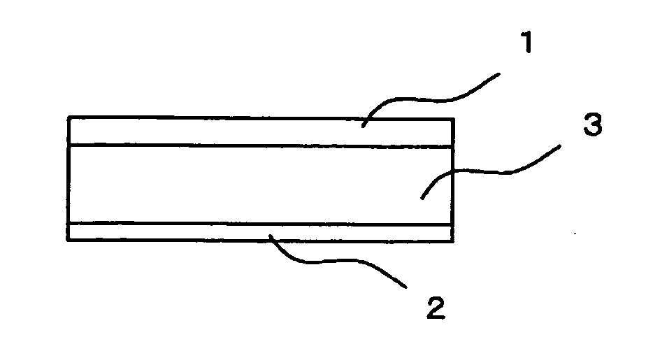
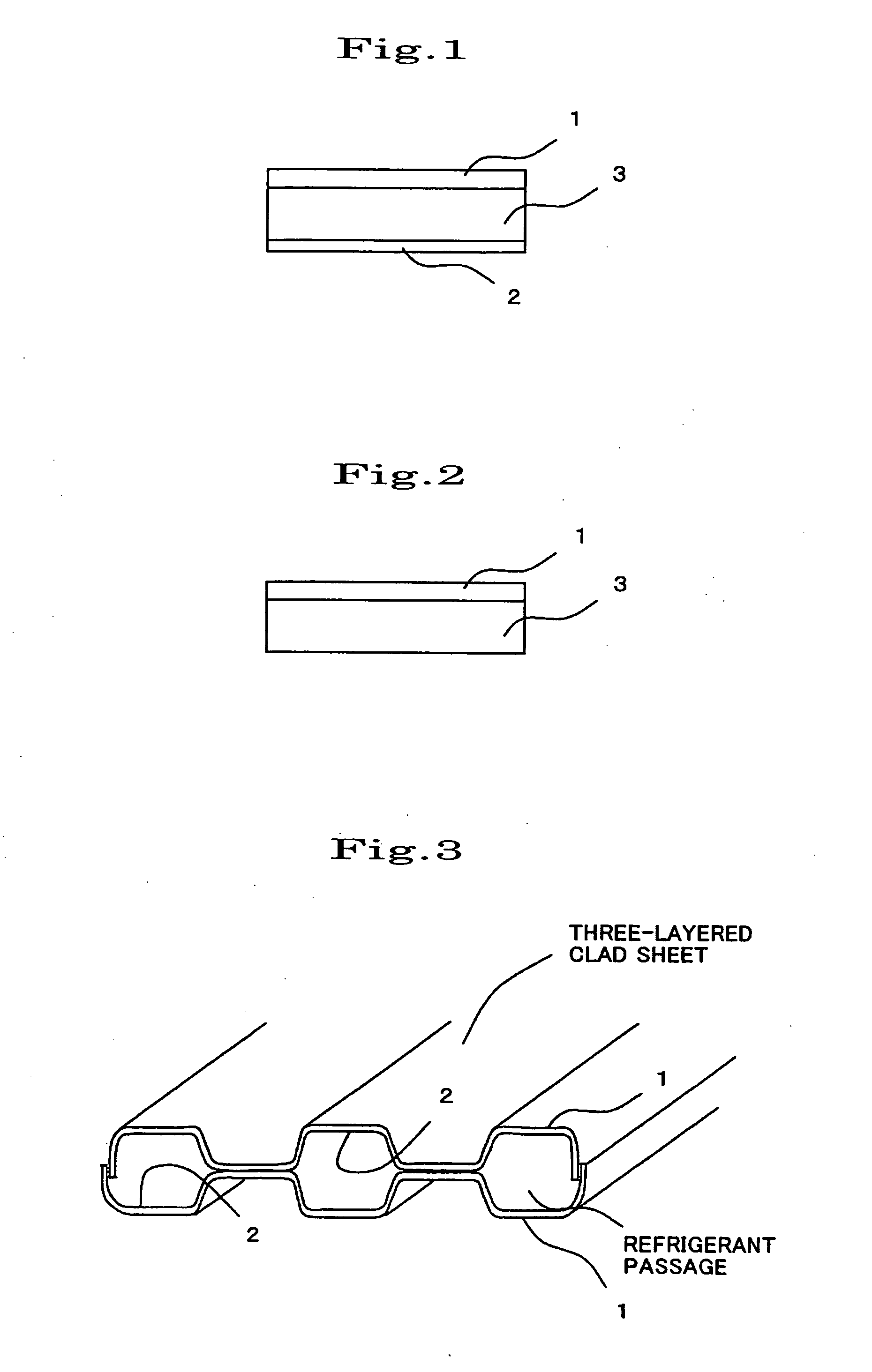
[0064]An aluminum alloy for the cladding material 1 (outer-side cladding material) having a composition shown in Table 1 or 2, an aluminum alloy for the core material shown in Table 3 or 4, and an aluminum alloy for the cladding material 2 (inner-side cladding material) having a composition shown in Table 5 or 6 were continuously cast, and homogenized by a normal method. The aluminum alloy for the cladding material 1 and the aluminum alloy for the cladding material 2 were then hot-rolled, and placed on the aluminum alloy for the core material according to the combination shown in Table 7 or 8 so that the thickness ratio of the cladding material 1, the core material, and the cladding material 2 was 20% / 70% / 10%. The aluminum alloys w...


PUM

PropertyMeasurementUnit
elongationaaaaaaaaaa
temperatureaaaaaaaaaa

Abstract

An aluminum alloy clad sheet for heat exchangers includes a core material, a cladding material 1, and a cladding material 2, one side and the other side of the core material being respectively clad with the cladding material 1 and the cladding material 2, the core material containing 0.5 to 1.2% of Si, 0.2 to 1.0% of Cu, and 1.0 to 1.8% of Mn, with the balance being Al and unavoidable impurities, the cladding material 1 containing 3 to 6% of Si, 2 to 8% of Zn, and at least one of 0.3 to 1.8% of Mn and 0.05 to 0.3% of Ti, with the balance being Al and unavoidable impurities, and the cladding material 2 containing 6 to 13% of Si, with the balance being Al and unavoidable impurities, the cladding material 1 being positioned on the outer side of the aluminum alloy clad sheet during use.

Description

BACKGROUND OF THE INVENTION[0001]The present invention relates to an aluminum alloy clad sheet for heat exchangers that exhibits excellent brazability and outer-side corrosion resistance, and is suitably used as a tube material or a tank or header material for an aluminum alloy heat exchanger that is produced by inert-gas brazing using a fluoride flux, and also relates to a method of producing the same.[0002]An aluminum alloy that is lightweight and exhibits excellent thermal conductivity is normally used for automotive heat exchangers (e.g., evaporator or condenser). A heat exchanger is normally produced by forming a refrigerant (i.e., working fluid) tube by bending a sheet material or layering sheet materials formed by press working, assembling a member such as a fin material with the refrigerant tube to form a given structure, and brazing the components in an inert gas atmosphere using a fluoride flux.[0003]In recent years, a reduction in weight has been desired for automotive he...

Claims


Application Information

Patent Timeline
Patent Type & Authority Applications(United States)
IPC IPC(8): C22F1/057C22C21/12
CPCB23K1/0012B23K35/22B23K35/286B23K35/288F28F21/084B32B15/016C22C21/00C22C21/02F28F1/022B23K2201/14B23K2101/14
Inventor HISATOMI, YUJIYAMASHITA, NAOKIITOH, YASUNAGA
Owner SUMITOMO LIGHT METAL INDS LTD
Learn More