High-pressure electrolysis installation and process for inertising an installation of this type

a technology of electrolysis installation and inertisation process, which is applied in the direction of electrical-based machining apparatus, photosynthesis process, instruments, etc., can solve the problems of loss of hydrogen contained in the first separator b>7/b> during inertisation, and the electrolysis installation involves progressive destruction of water which it contains, so as to reduce the maintenance cost of the electrolysis installation and simplify the design of the invention.

Inactive Publication Date: 2010-10-21
SWISS HYDROGEN POWER SHP
View PDF5 Cites 12 Cited by
  • Summary
  • Abstract
  • Description
  • Claims
  • Application Information

AI Technical Summary

Benefits of technology

[0010]It will be understood that according to the present invention, the hydraulic supply means of the installation are used to supply the inertising fluid for the separators. This feature means that it is not necessary to provide a pressurised nitrogen reserve, and this greatly reduces the maintenance costs of the electrolysis installation.
[0011]Furthermore, the hydraulic supply means are the same ones as are provided to replenish the cold water of the recirculation circuit 11 in normal operation. The fact that the same equipment is used during the extinguishing phase and during the normal operating phases allows the design of the invention to be greatly simplified.

Problems solved by technology

The operation of the electrolysis installation involves progressive destruction of the water which it contains.
First, the extinguishing means make it necessary to have a large amount of pressurised nitrogen available.
Furthermore, the hydrogen contained in the first separator 7 is lost during inertisation because it is mixed with a large amount of nitrogen and then released into the atmosphere.

Method used


Image

  • High-pressure electrolysis installation and process for inertising an installation of this type
  • High-pressure electrolysis installation and process for inertising an installation of this type
  • High-pressure electrolysis installation and process for inertising an installation of this type

Examples


first embodiment

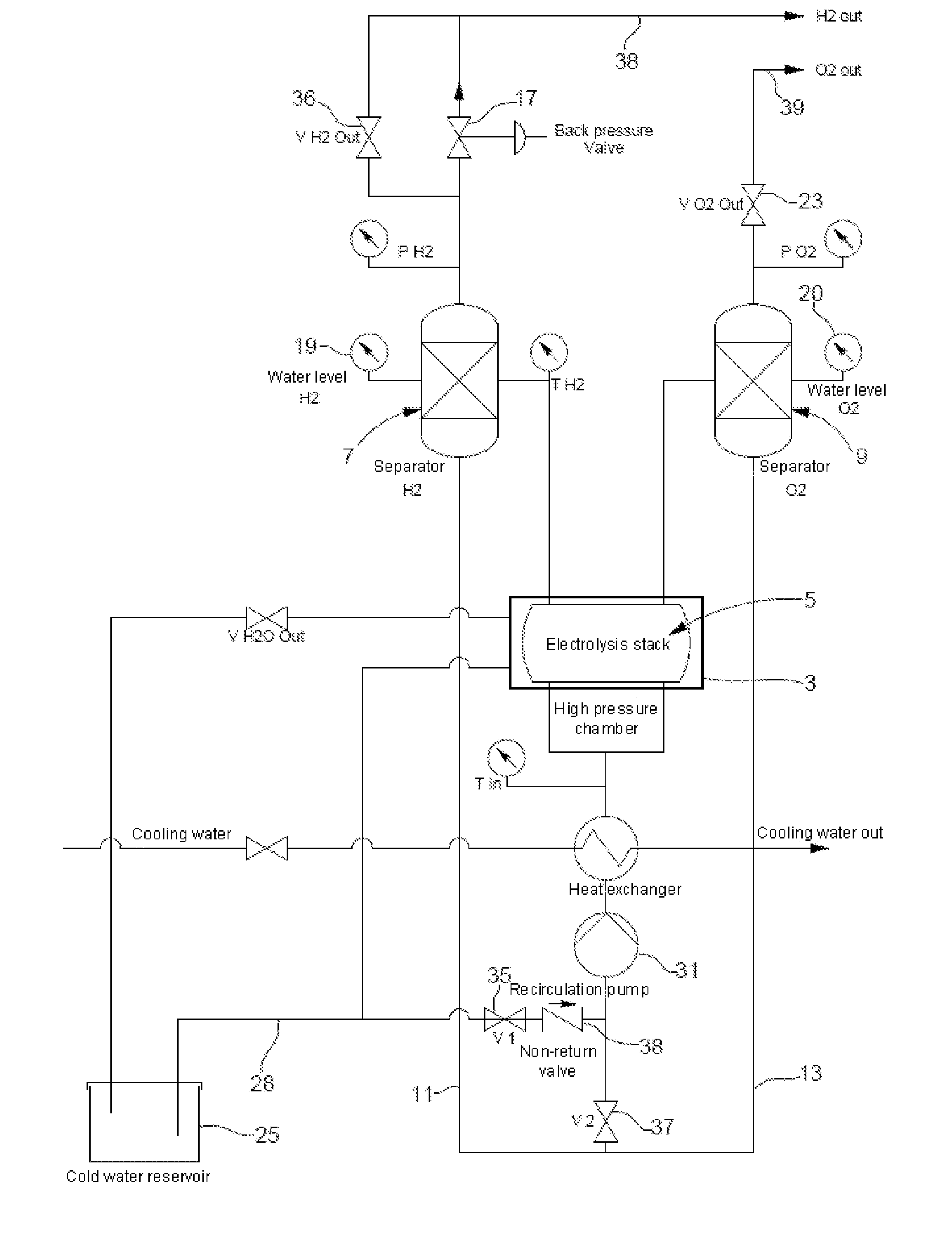
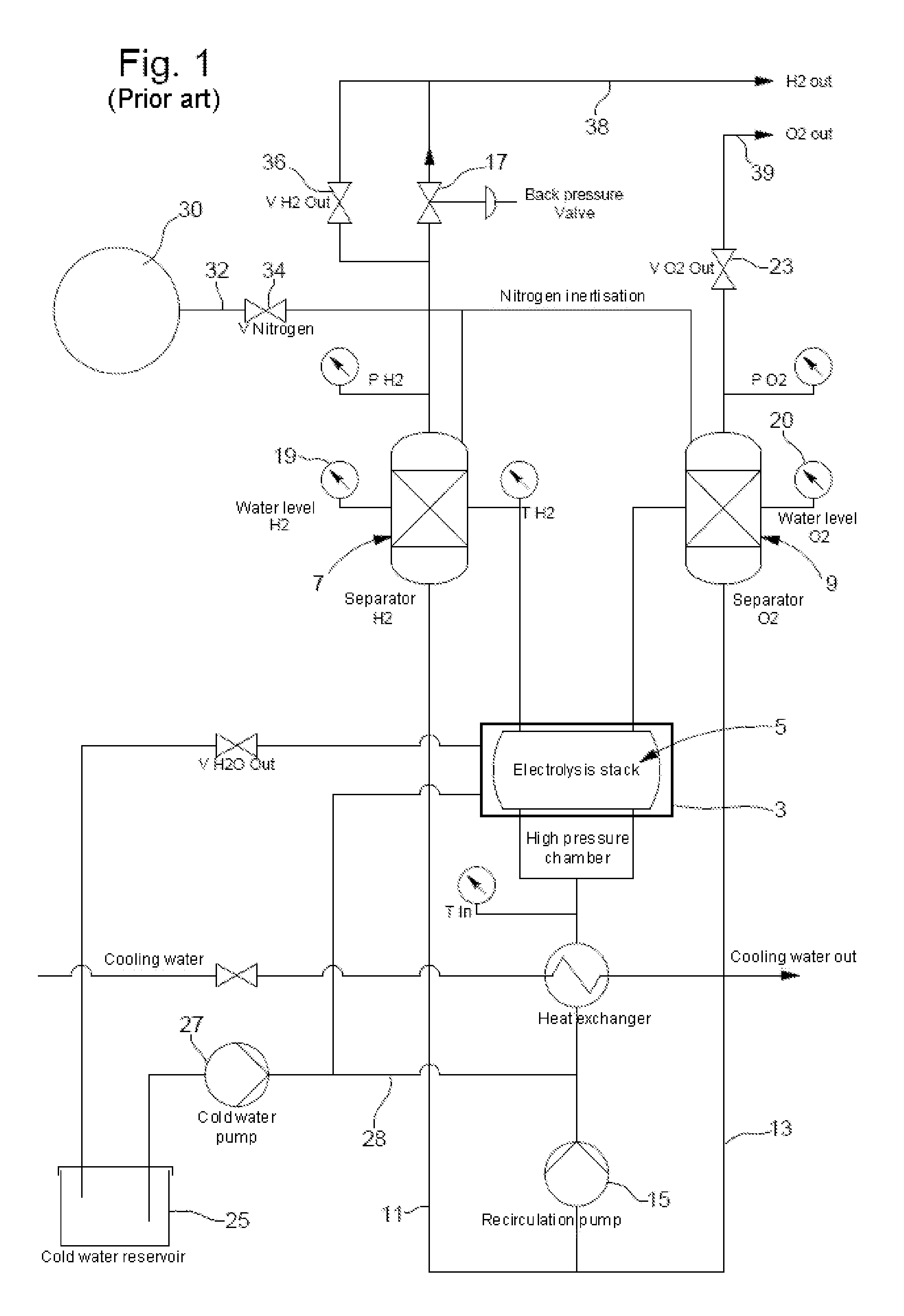
[0025]Simply removing the nitrogen reserve 30, the supply pipe 32 and the valve 34 from the diagram of FIG. 1 provides a schematic representation of a simplified electrolysis installation corresponding to the present invention.

[0026]Apart from the extinguishing phase, the electrolysis installation shown in FIG. 1 operates on exactly the same principle as the prior art installation described above. The only difference lies in the extinguishing phase and the means associated with this phase. In fact, in the present example, when the extinguishing of the installation is triggered, either automatically or by an operator, the pressure relief valves 36 and 23 are opened in a controlled manner so as to relieve the pressure in the two separators simultaneously, while keeping the water level inside said separators substantially constant. The hydrogen and oxygen released by the valves 36 and 23 leave the installation via the exhaust pipes 38 and 39 respectively in order to be recovered. The e...

second embodiment

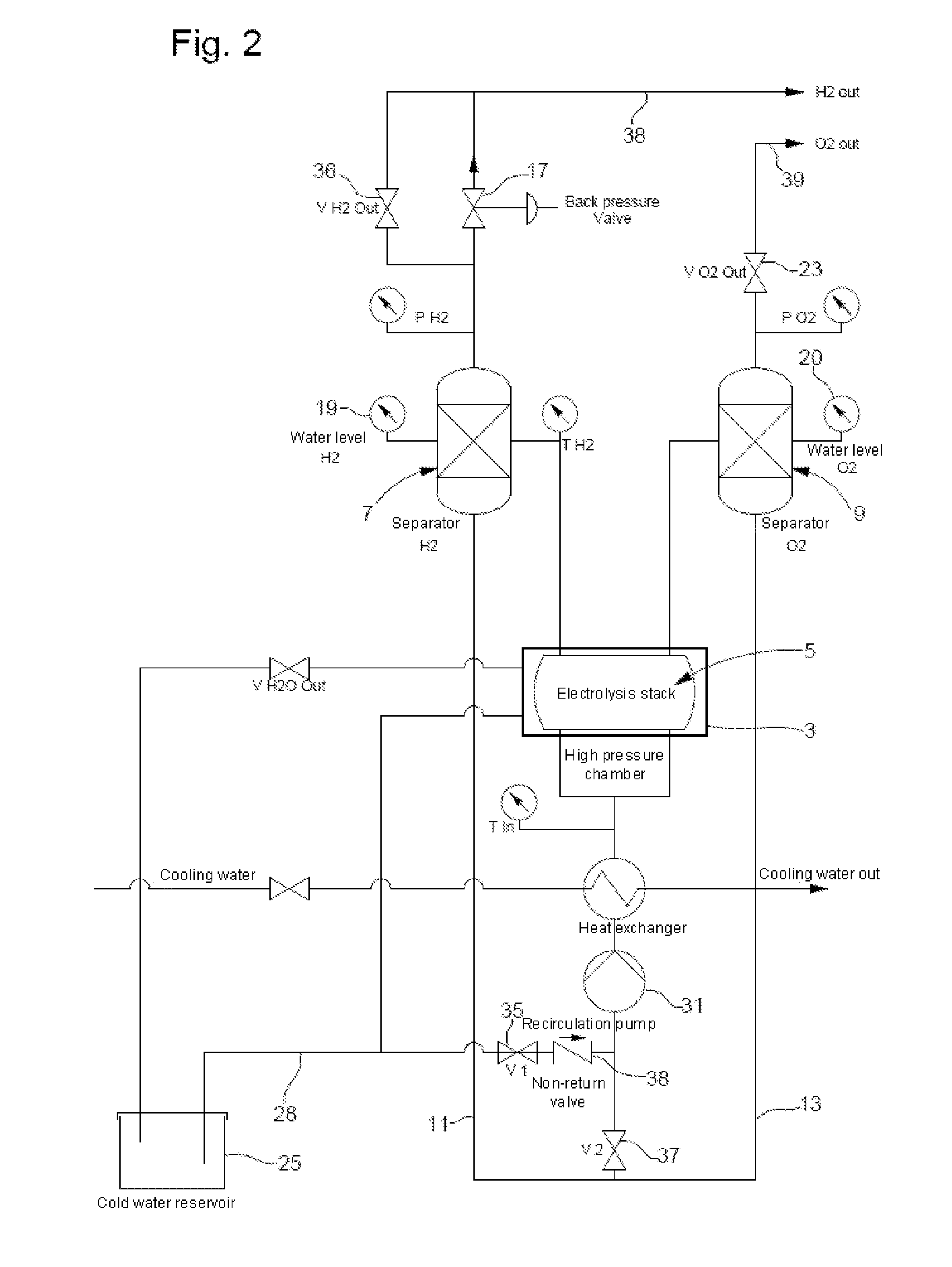
[0028]FIG. 2 is a schematic representation of an electrolysis installation according to the present invention. In FIG. 2, the components already described in connection with FIG. 1 have been provided with the same reference numerals.

[0029]The electrolysis installation shown in the drawing of FIG. 2 basically differs from that shown in FIG. 1 in that just one single pump 31 takes on the functions of a recirculation pump and of a supply pump.

[0030]For this purpose, the pump 31 is placed downstream from the junction between the pipe 28 and the recirculation circuit 13. The drawing shows that a supply valve 35 is mounted on the circuit 28 in the position where the supply pump 27 was located in the first embodiment. Moreover, a second valve 37 and a non-return valve 38 are mounted on the recirculation circuit upstream from the junction between said circuit and the pipe 28. It will be noted that the anti-return valve can be omitted. It will be understood that by controlling the relative o...


PUM

PropertyMeasurementUnit
hydrogen pressureaaaaaaaaaa
pressureaaaaaaaaaa
pressureaaaaaaaaaa

Abstract

The invention relates to an electrolysis installation for decomposing water into hydrogen and oxygen, comprising: an electrolysis stack (5); a water recirculation system supplying water to the stack, the recirculation system comprising a circuit (11, 13) and a recirculation pump (15), a first and a second separator (7, 9) for separating from the water the hydrogen and the oxygen respectively produced in the stack (5); a hydraulic supply means which supply the recirculation circuit (11, 13) with deionised water so as to compensate for the water consumed by the production of gaseous hydrogen and oxygen, and an extinguishing means for inertising the first and second separators (7, 9) when the installation is shut down, characterised by extinguishing means which comprise a first and a second relief valve (36, 23) provided on the first and second separators (7, 9) respectively, the valves being provided to relieve the pressure in the two separators simultaneously while keeping the water level inside the two separators substantially constant, and by extinguishing means which control the supply means so as to completely fill the two separators (7, 9) with water once the two separators have been relieved of pressure.

Description

[0001]This is a National Phase Application in the United States of International Patent Application No. PCT / EP2008 / 005583 filed Jul. 9, 2008 which claims priority on European Patent Application No. 07112288.1 filed Jul. 11, 2007. The entire disclosures of the above patent applications are hereby incorporated by reference.FIELD OF THE INVENTION[0002]The present invention relates to a high-pressure electrolysis installation for decomposing water into hydrogen and oxygen. It relates more specifically to an installation of this type comprising an electrolysis stack consisting of a plurality of electrolytic cells, each comprising an anode and a cathode. The installation further comprises a water recirculation system supplying water to said anodes and cathodes. The recirculation system itself comprises a water recirculation circuit, a recirculation pump, a first separator for separating the water and the gaseous hydrogen produced in the electrolysis stack and a second separator for separa...

Claims


Application Information

Patent Timeline
Patent Type & Authority Applications(United States)
IPC IPC(8): C25B1/04
CPCC25B1/12Y02E60/366C25B15/08C25B1/04C25B9/05Y02E60/36
Inventor DURET, ALEXIS
Owner SWISS HYDROGEN POWER SHP
Why Eureka
Try Eureka