Shock mount assembly and detector including the same

a technology of shock mount and detector, applied in the direction of shock absorbers, instruments, mechanical equipment, etc., can solve the problems of thermal coupling being broken when shear forces are applied, damage to the detector array, and thermal interface being subject to shear loading

Inactive Publication Date: 2010-10-21
GENERAL ELECTRIC CO
View PDF26 Cites 21 Cited by
  • Summary
  • Abstract
  • Description
  • Claims
  • Application Information

AI Technical Summary

Benefits of technology

[0007]In another embodiment, a method of dampening shock forces applied to a detector is provided. The detector includes an electronic assembly including a panel and a circuit board, a panel support rigidly coupled to the electronic assembly, and a casing surrounding the electronic assembly and the panel support. The method includes determining a distance between the panel and the casing, and configuring an isolator to have a dynamic stiffness that provides dynamic stiffness in three different directions, the dynamic stiffness being selected to limit the movement of the panel with respect to the casing to a quantity that is less than the distance between the panel and the casing.

Problems solved by technology

The resultant shock may cause the detector array to contact the external casing and thus damage the detector array.
The heat generating components are thermally coupled to the casing via a thermal compound that is not shear resistant, meaning that the thermal coupling can be broken when shear forces are applied.
Thus, if the x-ray detector experiences a shock event, the thermal interface may be subjected to shear loading and may become less effective at conducting heat.

Method used


Image

  • Shock mount assembly and detector including the same
  • Shock mount assembly and detector including the same
  • Shock mount assembly and detector including the same

Examples


Embodiment Construction

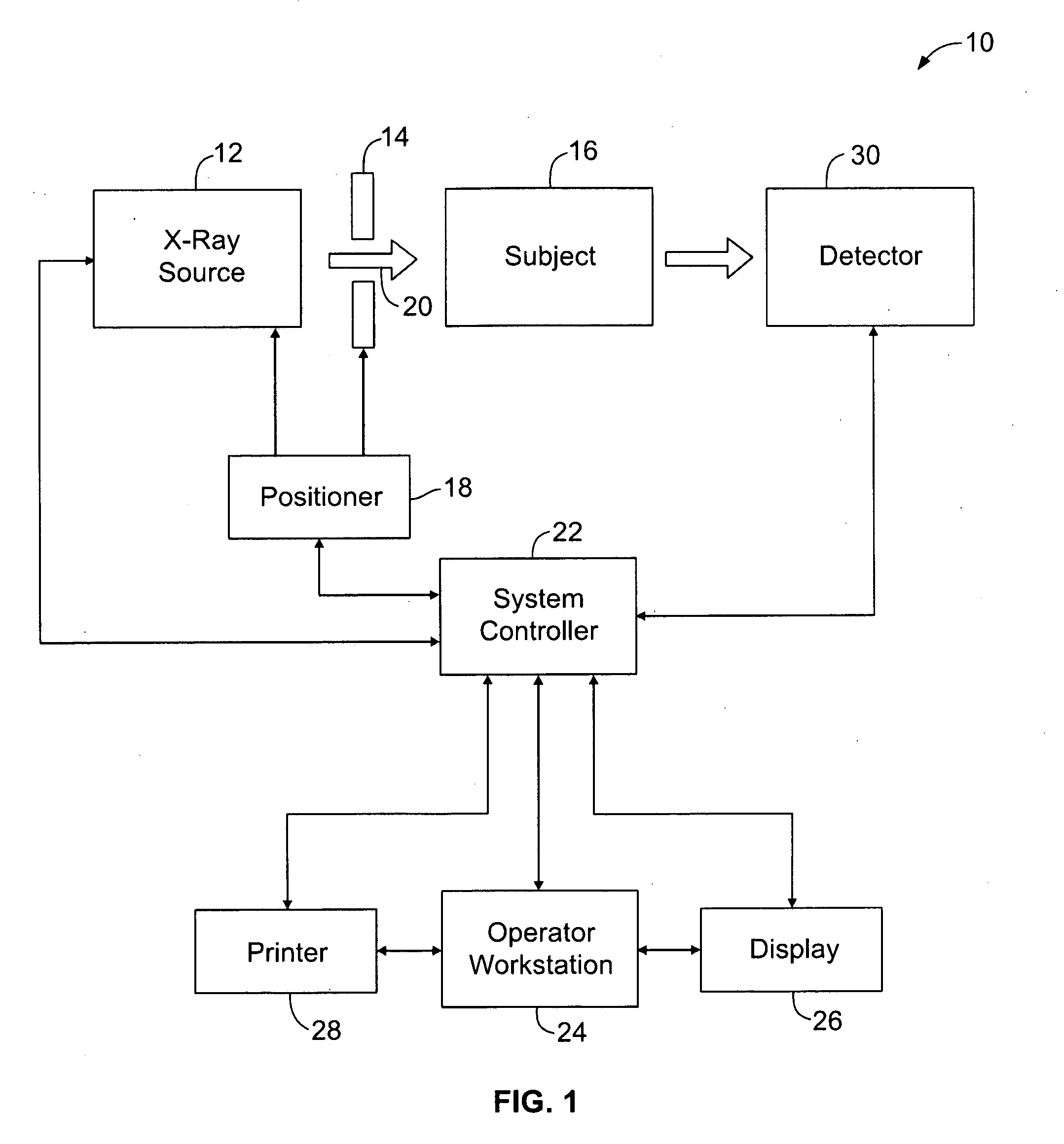
[0023]The foregoing summary, as well as the following detailed description of certain embodiments of the present invention, will be better understood when read in conjunction with the appended drawings. To the extent that the figures illustrate diagrams of the functional blocks of various embodiments, the functional blocks are not necessarily indicative of the division between hardware circuitry. Thus, for example, one or more of the functional blocks (e.g., processors or memories) may be implemented in a single piece of hardware (e.g., a general purpose signal processor or a block of random access memory, hard disk, or the like). Similarly, the programs may be stand alone programs, may be incorporated as subroutines in an operating system, may be functions in an installed software package, and the like. It should be understood that the various embodiments are not limited to the arrangements and instrumentality shown in the drawings.

[0024]As used herein, an element or step recited i...


PUM


Abstract

A shock mount assembly includes a base member, a top member, and an isolator disposed between the base member and the top member, the isolator providing a dynamic stiffness in three different directions to limit the movement, deflection, and / or acceleration of a detector array with respect to a casing surrounding the detector array in three dimensions. A detector array including the shock mount assembly is also described herein.

Description

BACKGROUND OF THE INVENTION[0001]The subject matter disclosed herein relates generally to detector devices, and more particularly to an apparatus providing shock protection to electronic assemblies in a detector device.[0002]In various portable x-ray medical imaging applications, an air-cooled x-ray detector is sealed in an external casing that is typically formed of metal. The x-ray detector includes a detector array that is formed on a breakable glass panel. The detector array is affixed directly or indirectly to a circuit board that includes heat generating components. If the x-ray detector is dropped, a shock is delivered to the external casing. The resultant shock may cause the detector array to contact the external casing and thus damage the detector array. As such, isolation of the detector array relative to the external casing is required to isolate the detector array from shock.[0003]Additionally, the x-ray detector includes a thermal interface to facilitate conducting heat...

Claims


Application Information

Patent Timeline
Patent Type & Authority Applications(United States)
IPC IPC(8): F16F1/00F16F7/00H01J5/02
CPCF16F1/38
Inventor KONKLE, NICHOLAS RYAN
Owner GENERAL ELECTRIC CO
Why Eureka
Try Eureka