Branch current monitoring system

a monitoring system and current technology, applied in the direction of resistance/reactance/impedence, dynamo-electric motor meters, instruments, etc., can solve the problems of burdensome interconnection of a significant number of power meters and in particular voltage connections to wires, and the circuit breaker will trip,

Active Publication Date: 2010-10-21
VERIS INDS
View PDF2 Cites 22 Cited by
  • Summary
  • Abstract
  • Description
  • Claims
  • Application Information

AI Technical Summary

Benefits of technology

[0009]Referring also to FIG. 4, the sensors 60 may be arranged such that the housings surrounding the current sensors have an overlapping region 70 in a substantially perpendicular direction with respect to the longitudinal axis of the support 62 and / or general alignment of the sensors. Preferably, the openings 64 defined by the sensors 60 are in a non-overlapping relationship 72 with respect to one another and a non-overlapping relationship 74 with respect to other housings. This permits the sensors to be arranged in a more compact arrangement within the power panel.
[0010]Referring also to FIG. 5, a respective transient voltage suppressor 80 may be interconnected in parallel across the output terminals of each sensor 60. The transient voltage suppressors 80 limits the voltage build up at the terminals of the sensors 60, which may occur if the sensors are sensing a changing magnetic field while the terminals of the sensors 60 are open circuited. This decreases the likelihood that technicians will be the recipient of an unanticipated electrical shock.

Problems solved by technology

In this manner, if a load shorts and thereafter draws excessive current then the circuit breaker will trip.
Unfortunately, it is burdensome to interconnect a significant number of power meters and in particular the voltage connections to the wires, especially if an interconnection to the wires are not readily available.
In addition, it is burdensome to interconnect the output of the power meters, if any, to a computer network because of the need to provide communication wiring or other wireless communication channels to each of the remotely located power meters.
Also, installing the power meters requires significant expense for the technician to locate a suitable location near each device, in addition to the further expense of servicing the installed power meters.
It takes considerable time to install, at significant expense, all of the current sensors 20 and the available space within the power panel 10 may be insufficient for the desired number of current sensors.
Also, the limited space available along the circuit breakers 16 may result in significant difficulty installing the current sensors 20, thus requiring lateral spacing of the current sensors and bending the wires from the circuit breakers to different locations within the power panel 10 in an attempt to locate sufficient available space for the current sensors 20.
Moreover, it is problematic to ensure that the wires 22 indicated by the installer that relate to a particular current sensor 20 actually are interconnected to the desired current sensor 20.
In summary, the potential installation problems are significant, especially when install by untrained technicians.
This decreases the likelihood that technicians will be the recipient of an unanticipated electrical shock.
While such a set of supports 62 with respective sensors 60 are suitable for use with new installation, it is difficult to install such a set of sensors 60 to an existing set of circuit breakers with wires already installed.
This significant imbalance in the current supplied by the different phases is sub-optimal.
For example, the greater the current levels the greater the voltage drop from the power source to the power panel, which may result in significant variations in the voltage levels provided to the power panel from the three phase power source.

Method used


Image

  • Branch current monitoring system
  • Branch current monitoring system
  • Branch current monitoring system

Examples


Embodiment Construction

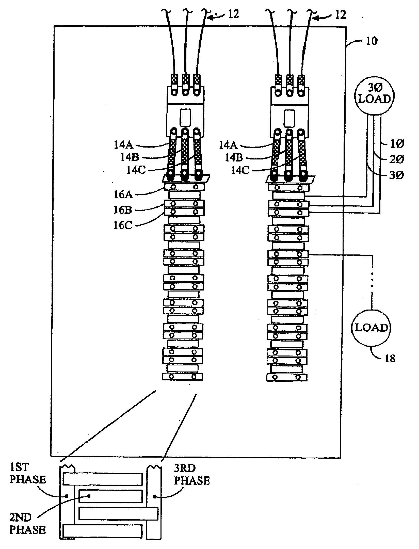
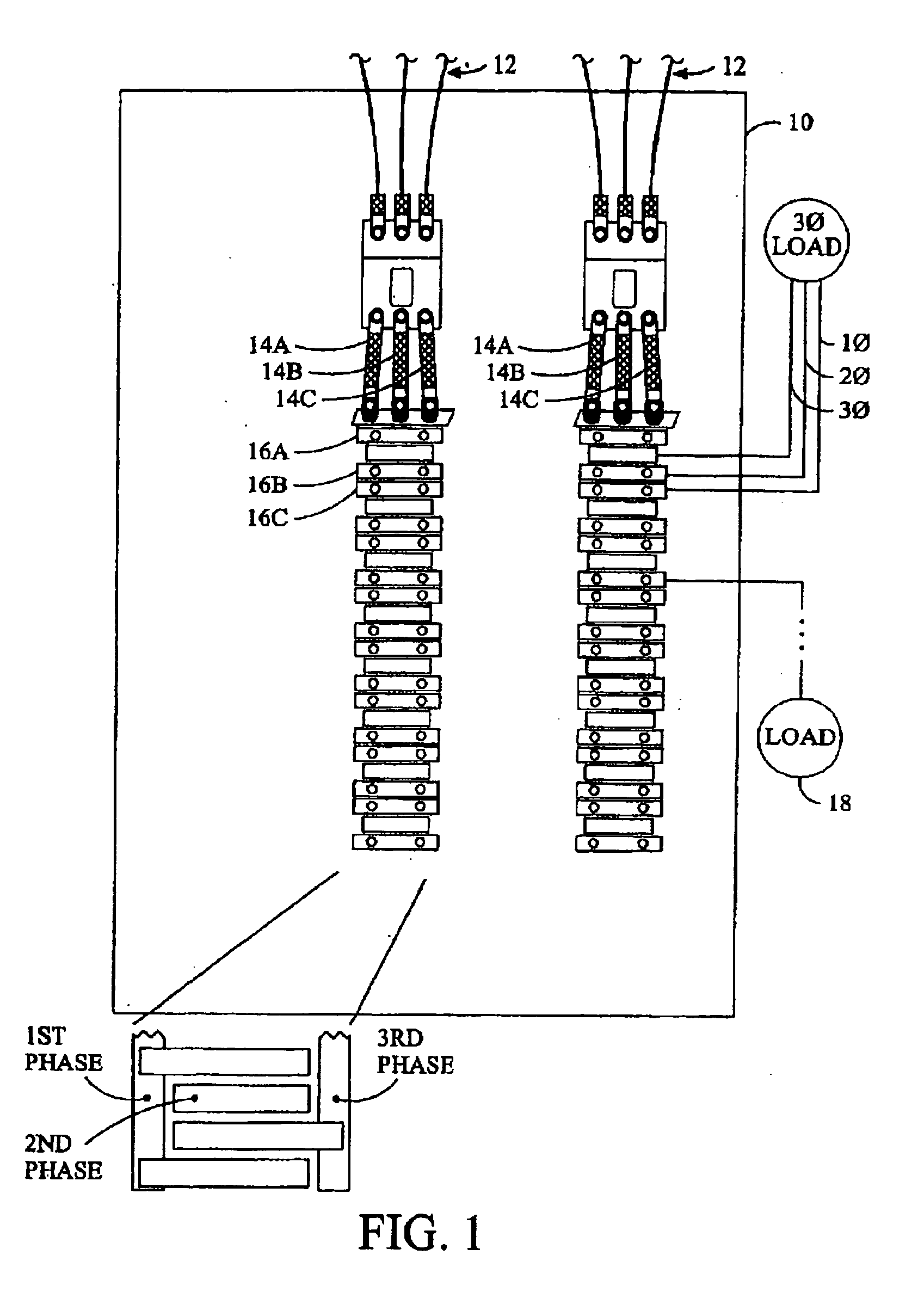
[0027]Upon reflection of the existing systems, the connector associated with the power meter board includes a lot of pins, each of which is relatively expensive and requires a corresponding cable with a large matching number of electrical paths. In addition, the connector also includes a burden resistor for each corresponding electrical paths associated with a current transformers. In total, the connectors, cables, and burden resistors require substantial space at significant expense.

[0028]Each of the current sensors on the supports includes an associated transient voltage suppressor. The transient voltage suppressors suppress voltage spikes from the open ended current transformers, which could be over 1,000 volts, thereby increasing safety. Unfortunately, the transient voltage suppressors are relatively expensive, especially with a corresponding transient voltage suppressor for each current transformer. The support preferably includes four or more current transformers.

[0029]Referri...


PUM


Abstract

A power monitoring system that reduces the need for transient voltage suppressors while using current transformers on an associated support operating using a current mode.

Description

CROSS-REFERENCE TO RELATED APPLICATIONS[0001]This application claims the benefit of Provisional App. No. 61 / 214,245, filed Apr. 20, 2009.BACKGROUND OF THE INVENTION[0002]The present invention relates to a branch current monitoring system.[0003]Referring to FIG. 1, many electrical power distribution systems include a panel enclosure 10 into which is provided electrical power using one or more sets of wires 12. The electrical power may have any voltage, any current, and any number of phases (e.g., single phase, two phases, or three phases). Each phase of the electrical power to the power panel is normally provided to a separate bus bar 14a, 14b, and 14c, which are normally elongate conductors within the power panel 10. A plurality of circuit breakers 16a, 16b, and 16c, etc., which trip or otherwise selectively disconnect electrical power, are electrically interconnected between one or more of the bus bars 14a, 14b, and 14c, and respective loads 18 external to the power panel 10. In ma...

Claims


Application Information

Patent Timeline
Patent Type & Authority Applications(United States)
IPC IPC(8): G01R27/08
CPCG01R11/02G01R21/06G01R15/142
Inventor RUPERT, MATTHEW
Owner VERIS INDS
Why Eureka
Try Eureka