Circuitry for processing signals from a higher voltage domain using devices designed to operate in a lower voltage domain

a technology of circuitry and signal processing, applied in the direction of pulse shaping, electric apparatus, pulse automatic control, etc., can solve the problems of difficult to set threshold levels, difficult to provide threshold levels that can be met, hysteresis into the apparatus, etc., to delay the switching of the device, the effect of well balanced

Active Publication Date: 2010-10-21
ARM LTD
View PDF9 Cites 12 Cited by
  • Summary
  • Abstract
  • Description
  • Claims
  • Application Information

AI Technical Summary

Benefits of technology

[0020]The switch delay device on the second input path reduces the voltage on the input signal delaying its switching and providing the required hysteresis.
[0046]The selecting circuitry can generate a hysteresis enable signal in response to an input requesting hysteresis. This input may be provided by a user. If cascoded output circuitry is used then one of the devices can be used as an enabling device and the other as a functional device. The enabling device can then be turned on or off in response to the enable signal and thus, either the second set or the additional second set can be rendered operational and the operational set is then the one used. The input signal for the second set comes from the second input path with the delay device when the connecting path is open and the input signal for the operational device of the additional second set comes from the first input and therefore has no delay.

Problems solved by technology

However, although this addresses the problem of the devices becoming overstressed, it raises its own problems with the threshold voltages that cause the apparatus to switch being low as they need to be within the low voltage domain.
As the apparatus is operating in the second lower voltage domain it is difficult to provide threshold levels that can be met at all times for the device to switch consistently particularly if hysteresis is added.
Thus, many designs insert hysteresis into the apparatus.
In the present case where higher value signals are received that need to be limited to the values of the lower voltage domain it can be difficult to set the threshold levels to appropriate values within this power domain that enable the devices to switch consistently with hysteresis.
It does not allow any space to add the 330 mV nominal hysteresis value and still be within safe limits.

Method used


Image

  • Circuitry for processing signals from a higher voltage domain using devices designed to operate in a lower voltage domain
  • Circuitry for processing signals from a higher voltage domain using devices designed to operate in a lower voltage domain
  • Circuitry for processing signals from a higher voltage domain using devices designed to operate in a lower voltage domain

Examples


Embodiment Construction

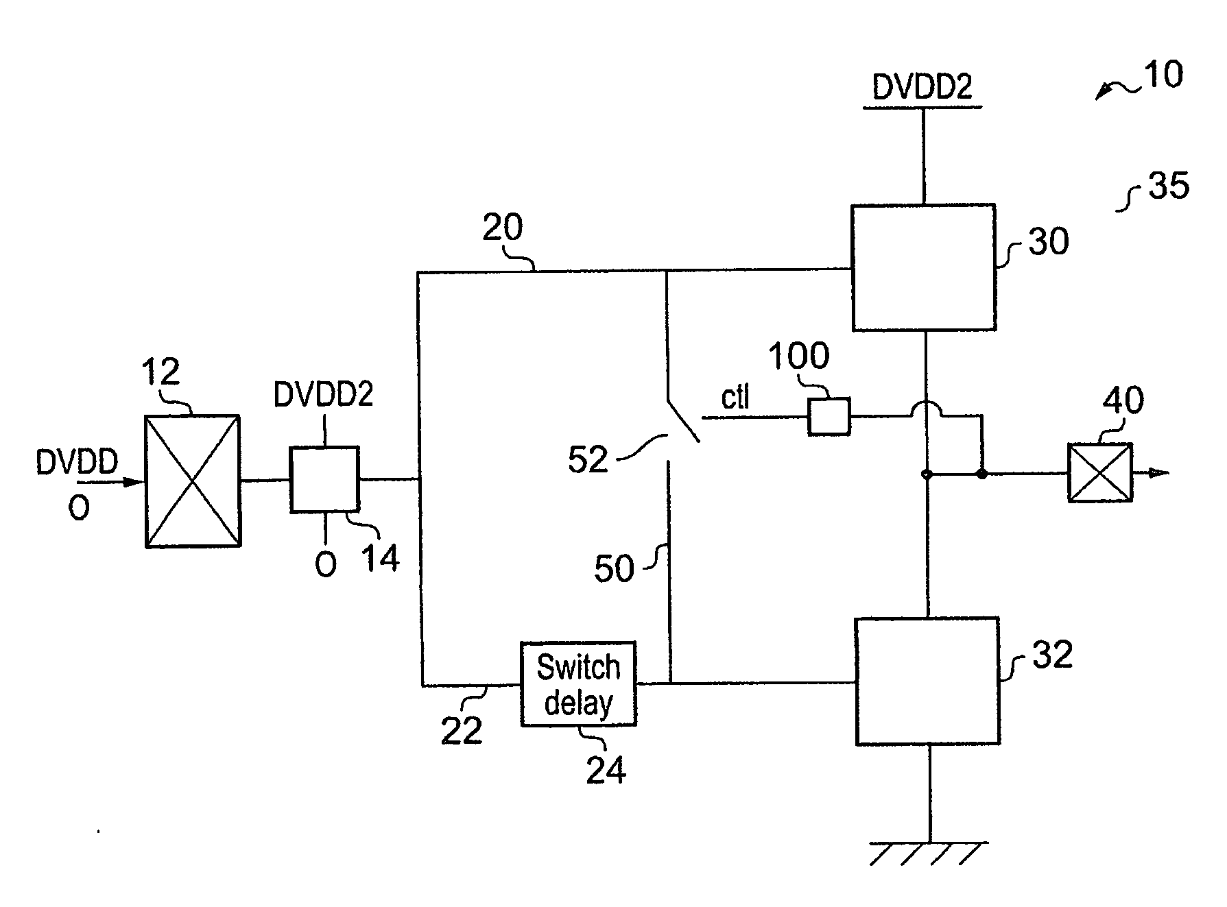
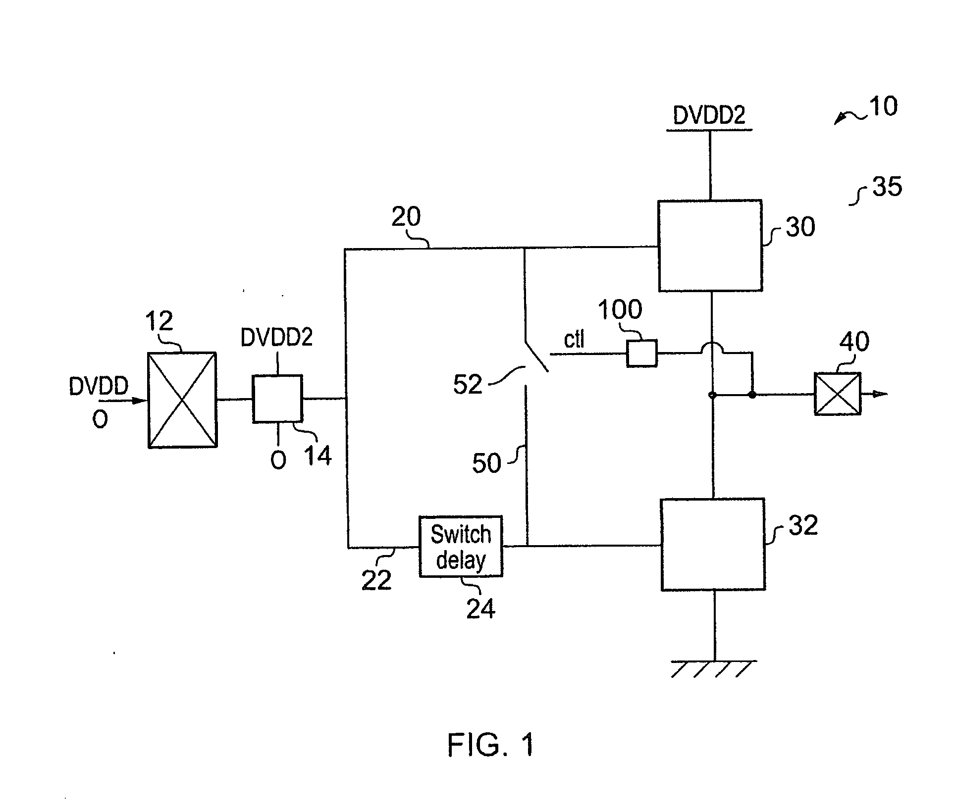
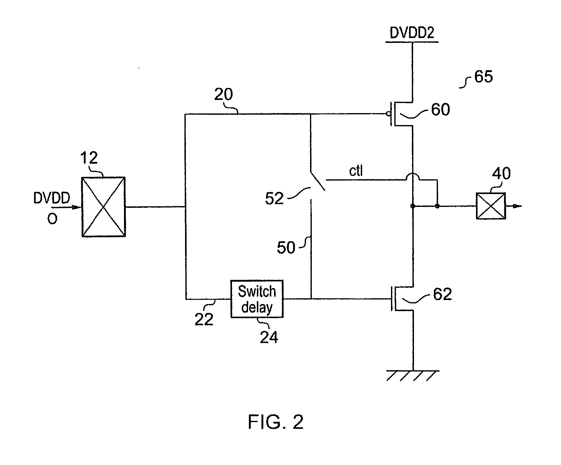
[0058]FIG. 1 shows a high voltage input-output receiver 10 for receiving signals of a high voltage domain and outputting into a lower voltage domain using devices of the lower voltage domain according to an embodiment of the present invention. This apparatus 10 has an input pad 12 for receiving an input signal in the higher voltage domain which has a high voltage level of DVDD. DVDD may typically be 3.3 Volts. There is then a voltage level controlling device 14 which acts to clamp the upper voltage to DVDD2 which is the voltage of the second lower voltage domain which the devices of apparatus 10 are designed to function within and which is the voltage domain of the circuitry to which the output signals are sent. This signal may for example have a high value of 1.8 Volts.

[0059]The apparatus 10 has two input paths for the received signal, first input path 20 and second input path 22. These signals are sent to output circuitry 35. First input path 20 goes to a first set of devices 30 t...


PUM


Abstract

An apparatus is disclosed for receiving input signals in a first higher voltage domain and for generating and outputting signals in a second lower voltage domain, said apparatus comprising: an input pad for receiving said input signals in said first higher voltage domain; output circuitry comprising a plurality of devices arranged between a high voltage source of said second lower voltage domain and a low voltage source, said plurality of devices being arranged in a first set and a second set, said first set being arranged between said high voltage source and said output and said second set being arranged between said output and said low voltage source, said output circuitry being configured to switch to output a first predetermined value in response to a rising input signal exceeding an upper threshold value and to switch to output a second predetermined value in response to a falling input signal falling below a lower threshold value; a first input path for sending said received input signals to a first input of said first set; a second input path for sending said received input signals to a second input of said second set; wherein said second input path comprises a switch delay device for reducing a voltage of said received input signal such that on a rising input signal, said input signal has reached a higher value when said output circuitry switches in response to said input signal than it would have reached had said input signal voltage not been reduced; and a controllable connecting path between said first and second inputs for connecting said first and second inputs together in response to detection of said first predetermined value at said output and for not connecting said first and second inputs together in response to detection of said second predetermined value at said output.

Description

BACKGROUND OF THE INVENTION[0001]1. Field of the Invention[0002]The field of the invention relates to circuitry processing signals from a higher voltage domain using devices configured to operate in a lower voltage domain.[0003]2. Description of the Prior Art[0004]Advances in the field of electronics have led to a reduction in both core and input-output power supplies in order to increase processing speeds and reduce power consumption. The transistor dimensions and oxide thickness have also decreased for the same speed reasons.[0005]Thus, for devices of 45 nm, the “standard” external power is now 1.8V where it was previously 3.3V or 2.5V. In order to be able to reach high frequencies the oxide thickness has been decreased and is now around 28 to 32 Å for 1.8V devices (where previously it was about 50 Å).[0006]There are therefore now some apparatus that operate with the new devices in circuits that receive or generate signals in the old higher voltage domains. For example, to be comp...

Claims


Application Information

Patent Timeline
Patent Type & Authority Applications(United States)
IPC IPC(8): H03L5/00
CPCH03K5/08
Inventor DUBY, JEAN-CLAUDELEYMARIE, FLORAPADILLA, THIERRY
Owner ARM LTD
Why Eureka
Try Eureka