
Constant optical output illumination system

a constant optical output and illumination system technology, applied in the direction of fire alarms, instruments, electrical appliances, etc., can solve the problem that both of these night-time scenarios are far from optimal

Active Publication Date: 2010-10-21
BOSCH SECURITY SYST INC
View PDF2 Cites 17 Cited by
  • Summary
  • Abstract
  • Description
  • Claims
  • Application Information

AI Technical Summary

Benefits of technology

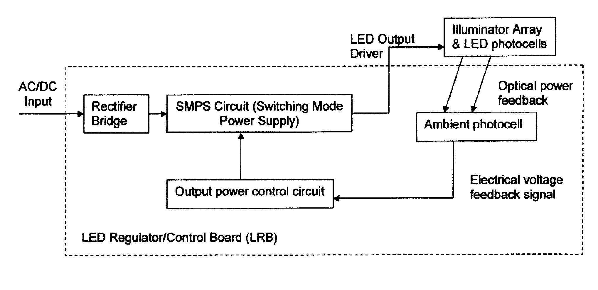
[0006]This invention provides a constant optical output illuminator system to enable reliable long-duration low-light imaging and data capture. This disclosure describes an illuminator for CCTV surveillance and security applications that maintains constant optical output from an array of LEDs by employing output compensation, feedback and enhancement. The constant illuminator system overcomes a number of problems with common LED illuminators where optical output varies:
[0017]The combined effects of manufacturing variance, temperature variation and lifetime degradation are additive, making a worst case variation in the region of + / −50% optical output power under various conditions. The constant illuminator system 20 will guarantee 100% constant optical power over the same conditions giving confidence in security system design.
[0018]By monitoring and maintaining optical power output from the illuminator, the quality of the CCTV image will not change over time and will therefore greatly enhance the image quality as well as extend the useful life of the security / surveillance system.
[0019]The constant illuminator system is designed to provide reliable long-duration illumination for low-light imaging and data capture. By packing higher power LEDs closer together and running them with less current, then making more efficient use of their light output by focusing through a lens, then an asymmetric diffuser, the resultant light output is at least equal to the prior art, but provides constant illumination over a much longer operational lifetime. Photodetectors also monitor total LED output and increase drive current or activate additional auxiliary LEDs to maintain optimal LED output longer than other solutions. Overheating is prevented by lowered operating current, pulse width modulation and by use of efficient heatsinking The constant illumination system may use surface mount or through-hole LEDs in either visible or infrared wavelengths, depending on the surrounding light available and monitoring equipment used.

Problems solved by technology

CCTV system installation is a challenging field where the performance of a surveillance system is measured not only by the resulting image quality, but the ability to maintain that quality in all environments, lighting conditions, and during the full lifetime of the product.
Both of these night-time scenarios are far from optimal when the quality of CCTV images for security and surveillance applications is considered.

Method used


Image

  • Constant optical output illumination system
  • Constant optical output illumination system
  • Constant optical output illumination system

Examples


Embodiment Construction

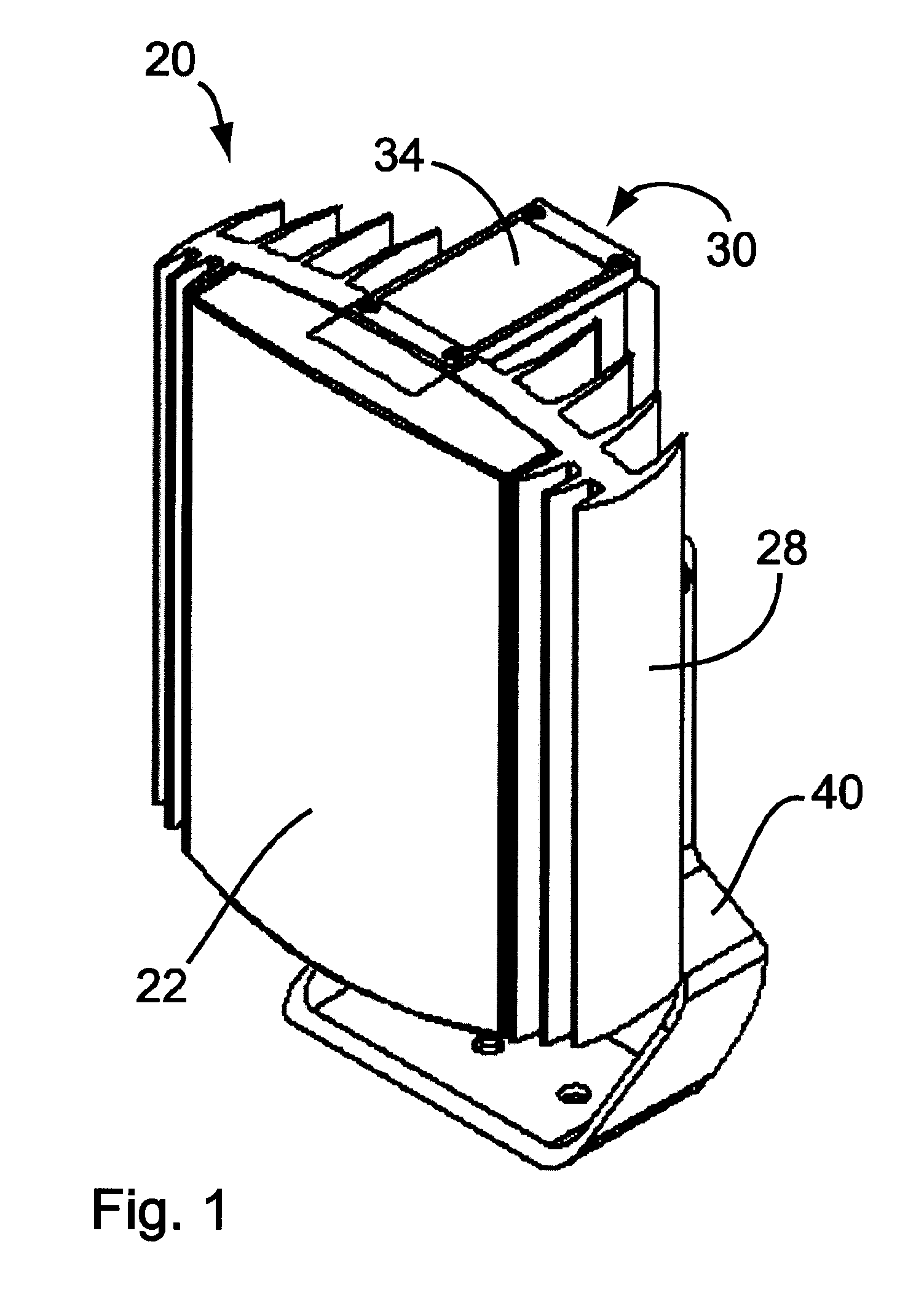
[0052]FIG. 1 shows the exterior of a constant illuminator system 20, with its faceplate 22, heatsink 28, mounting bracket 40, LRB (LED Regulator / Control Board) enclosure 30, and its top coverplate 34.

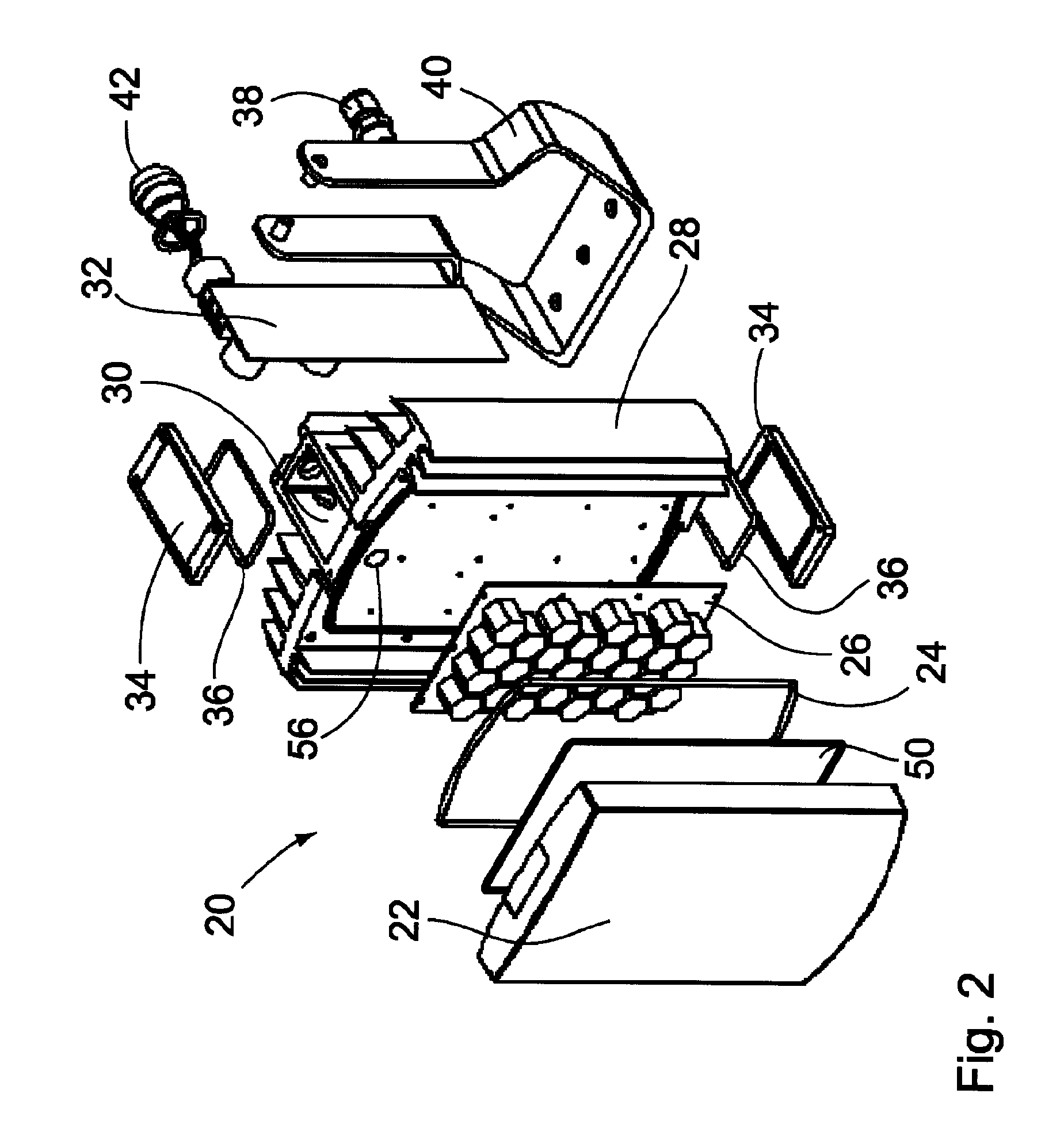
[0053]FIG. 2 shows an exploded view of the constant illuminator system 20, with its faceplate 22, micro-diffractor 50, faceplate gasket 24, and LED array board 26. The heatsink 28 and LRB enclosure 30 are cast as one unit, but are defined as separate functional elements. The elements listed above are assembled onto the front of the heatsink 28. Any heated gas or moisture from the LED array board 26 escapes through the internal wall of the heatsink 28, into the LRB enclosure 30. Pressure and moisture are then passed out of the LRB enclosure 30 by means of a pressure relief valve 38. The LRB enclosure 30 houses an LED regulator / control board (LRB) 32, sealed from external environments by means of a coverplate 34 and a gasket 36 with fasteners 52 (shown in FIG. 4). Attached to the LRB 32, ...


PUM


Abstract

The present invention is an illuminator for CCTV surveillance and security applications that maintains constant optical output from an array of LEDs by employing output compensation, feedback and enhancement. This constant optical output illuminator system enables reliable long-duration low-light imaging and data capture for surveillance and security applications, via an array of LEDs, LED power supply circuitry, and output feedback and compensation circuitry in which a photodetector circuit provides a voltage signal proportional to an amount of light falling on a photosensor and the voltage signal is fed to a drive control circuit for electrical current to the LEDs to achieve a desired optical output as measured by a photosensor voltage setpoint across the photodetector circuit.

Description

FIELD OF INVENTION[0001]This invention relates to the general field of surveillance illumination devices, particularly light emitting diode (LED) illumination devices, and power supplies for LEDs.BACKGROUND OF THE INVENTION[0002]Surveillance illuminator systems using arrays of LEDs mounted on metal heatsinks are widely used in the security industry to provide visible or infrared (IR) illumination for CCTV cameras, imaging or data capture devices. LED illuminators are claimed to offer lifetimes in excess of 100,000 hours, however their effective output decays from the moment the LEDs are activated. Lifetime output reductions of 20% to 50% have been quoted in manufacturer's data, and LED output is often specified at 50% of the maximum operating current at a particular ambient temperature. The need for increased illuminator range and output necessitates that LEDs be driven to their current limits in surveillance applications, a practice that reduces illuminator effectiveness, reliabili...

Claims


Application Information

Patent Timeline
Patent Type & Authority Applications(United States)
IPC IPC(8): G08B13/00H05B37/02G05B23/02G08B17/00H05B44/00
CPCH05B33/0854H05B33/0803H05B45/325H05B45/38H05B45/12H05B45/3725H05B45/375
Inventor MAYER, TONYVERNON, MARKREN, JIM
Owner BOSCH SECURITY SYST INC
Learn More