Hologram reproducing and imaging apparatus, and hologram reproducing and imaging method

a technology of hologram and imaging apparatus, which is applied in the field of hologram reproducing and imaging apparatus, and hologram reproducing and imaging method, can solve the problems of increasing the number of optical parts, and achieve the effect of small and simple optical system and low cos

Inactive Publication Date: 2010-10-21
SONY CORP +1
View PDF5 Cites 6 Cited by
  • Summary
  • Abstract
  • Description
  • Claims
  • Application Information

AI Technical Summary

Benefits of technology

[0027]According to an embodiment of the present invention, a clear reproduction image wit

Problems solved by technology

The method described in Japanese Unexamined Patent Application Publication No. 11-258970 does not solve the problem of the overlapped images when a plurality of LEDs are used as a lig

Method used


Image

  • Hologram reproducing and imaging apparatus, and hologram reproducing and imaging method
  • Hologram reproducing and imaging apparatus, and hologram reproducing and imaging method
  • Hologram reproducing and imaging apparatus, and hologram reproducing and imaging method

Examples


first embodiment

1. First Embodiment

Configuration of Replication Apparatus

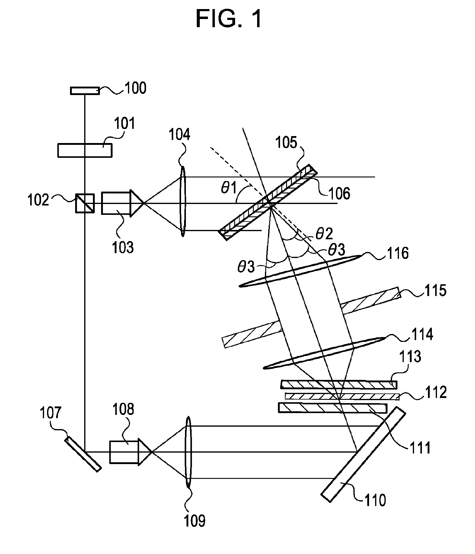
[0051]A replication apparatus to which an embodiment of the present invention can be applied will be described with reference to FIG. 1. The replication apparatus replicates a hologram from a hologram original plate to a hologram recording medium, and at the same time, records additional information such as a serial number and identification information.

[0052]Laser light from a laser light source 100 enters a polarizing beam splitter 102 through a half-wavelength plate 101. The half-wavelength plate 101 rotates a polarization plane of the laser light by 90°. The laser light (S-polarized light) is reflected by the polarizing beam splitter 102, and the laser light is spread by a spatial filter 103. The laser light (in other words, reference light) from the spatial filter 103 enters a collimation lens 104. The laser light which is converted into parallel light by the collimation lens 104 is irradiated to a hologram recording medi...

second embodiment

2. Second Embodiment

Imaging Optical System

[0102]The second embodiment of the present invention will be described. As a method for reading information recorded in a hologram, when capturing image by scanning the hologram, it is easy to capture a high resolution image because the image is captured in the same condition at least in the scanning direction. The reference light irradiating the hologram obliquely enters the hologram, and as the reference light, near parallel light should be uniformly irradiated from a position in an optical path reaching the hologram at a predetermined angle. Specifically, the reference light has to enter from the direction in which reference light entered when the hologram was produced.

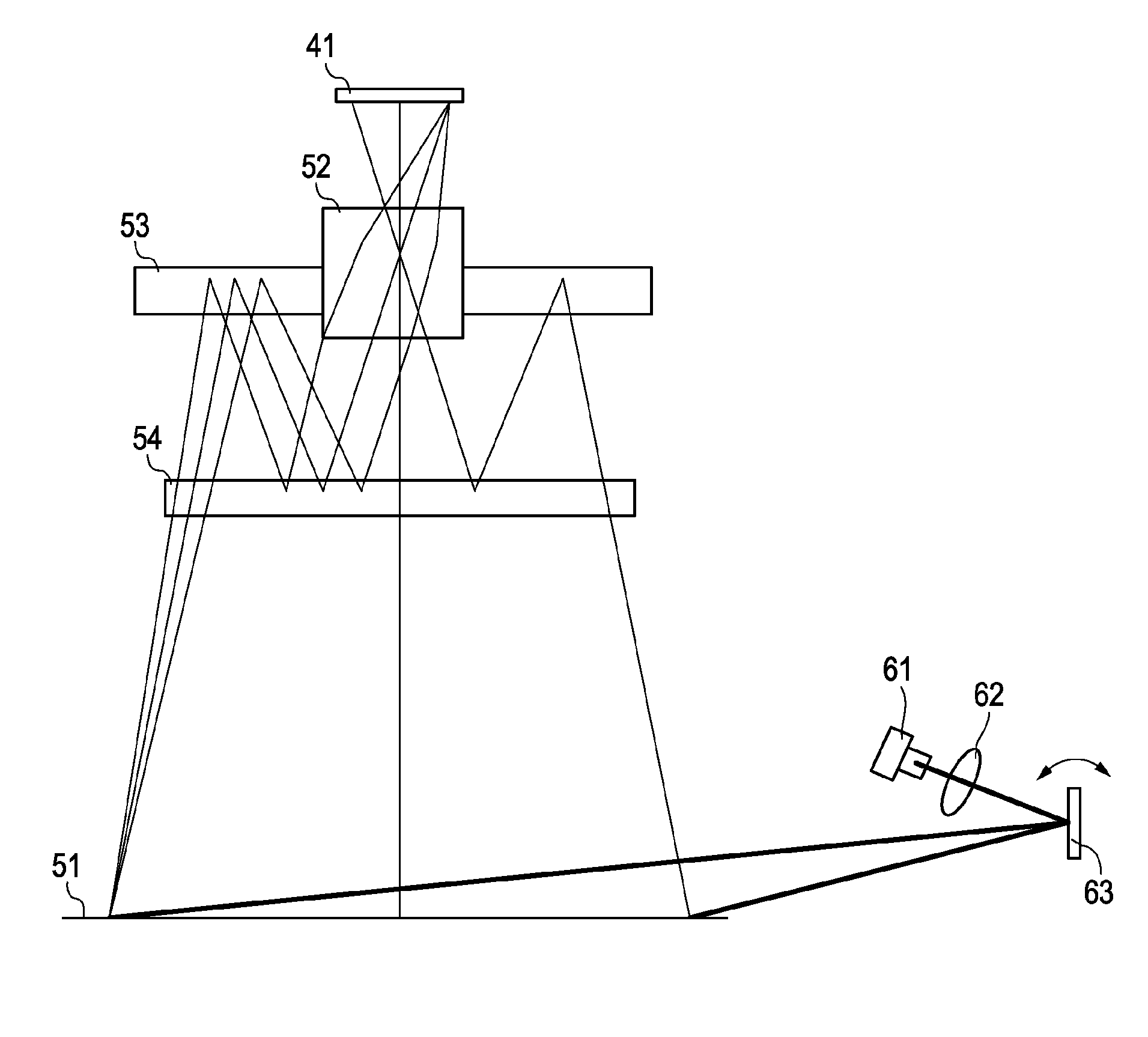
[0103]FIG. 14 illustrates a first example of the imaging optical system. FIG. 14A is a side view and FIG. 13B is a front view. The laser light from a laser light source 61 is converted into parallel light by a collimator lens 62, and hits a galvano mirror 63. Instead of the...


PUM


Abstract

A hologram reproducing and imaging apparatus includes a reference light source configured to be arranged near a hologram recording material on which a hologram is recorded and has an arrangement of a plurality of light sources, a reference light source drive section configured to drive the plurality of light sources in a time-division manner, an imaging sensor configured to capture an image of a reproduction area irradiated with reference light from the reference light source and photoelectrically convert the image, and an image processing section configured to process an imaging signal from the imaging sensor. Partial captured images are obtained by enabling the imaging signal of the area irradiated when the plurality of light sources are turned on, and the partial captured images are combined to be a reproduction image by the image processing section.

Description

BACKGROUND OF THE INVENTION[0001]1. Field of the Invention[0002]The present invention relates to a hologram reproducing and imaging apparatus and a hologram reproducing and imaging method for reproducing recorded information from a hologram recording material on which interference fringes of signal light (object light) and reference light are recorded, and photoelectrically converting the information.[0003]2. Description of the Related Art[0004]The hologram which can display a three-dimensional image is used to determine authenticity of a credit card, an identification card, and the like. Currently, many embossed type holograms, which record information by using surface unevenness of an interference film, are used. However, there is a problem that the embossed type hologram can be easily forged. On the other hand, a Lippmann type hologram which records information by using differences in refractive index in an interference film is very difficult to forge. This is because a sophistic...

Claims


Application Information

Patent Timeline
IPC IPC(8): G03H1/22
CPCG03H1/0248G03H1/04G03H1/0402G03H1/0406G03H1/20G03H1/202G03H1/22G03H1/2205G03H1/2286G03H1/265G03H1/268G03H2001/0016G03H2001/0415G03H2001/2223G03H2001/2236G03H2001/2244G03H2001/2247G03H2210/22G03H2210/32G03H2210/52G03H2210/54G03H2210/562G03H2222/34G03H2222/36G03H2223/14
Inventor SHIRAKURA, AKIRAISHIWATA, KOJIKISHIBATA, FUMIHISASUIGIURA, YOSHIHIROBABA, SHIGEYUKIYOSHIMURA, SHINICHI
Owner SONY CORP
Why Eureka
Try Eureka