Dual-cooled nuclear fuel rod having annular plugs and method of manufacturing the same

a nuclear fuel rod and annular plug technology, which is applied in nuclear engineering, nuclear elements, greenhouse gas reduction, etc., can solve the problems of dual-cooled nuclear fuel rods being considerably restricted, difficult to weld, and the center of the pellet not being able to transmit coolant to the coolant, so as to reduce the temperature of prevent damage to the nuclear fuel rod, and increase the thermal conductivity

Active Publication Date: 2010-10-21
KOREA ATOMIC ENERGY RES INST +1
View PDF12 Cites 5 Cited by
  • Summary
  • Abstract
  • Description
  • Claims
  • Application Information

AI Technical Summary

Benefits of technology

[0027]As described above, according to the dual-cooled nuclear fuel rod having annular plugs, the nuclear fuel rod is composed of two cladding tubes having different diameters and two end plugs, and a coolant is allowed to flow to the outside as well as the inside of the nuclear fuel rod, thereby rapidly transmitting heat from a pellet to the outside and inside of the nuclear fuel rod to increase thermal conductivity.
[0028]Further, due to an increase in area where the nuclear fuel rod comes into contact with a coolant, heat generated from a pellet is rapidly transmitted to the coolant, thereb...

Problems solved by technology

Thus, when the heat is generated through the nuclear fission chain reaction, the heat generated adjacent to an outer circumference of the pellet placed into contact with the coolant is easily transmitted to the coolant, whereas the heat generated from the center of the pellet fails to be transmitted to the coolant.
Further, in a dual-cooled nuclear fuel rod composed of two cladding tubes ha...

Method used


Image

  • Dual-cooled nuclear fuel rod having annular plugs and method of manufacturing the same
  • Dual-cooled nuclear fuel rod having annular plugs and method of manufacturing the same
  • Dual-cooled nuclear fuel rod having annular plugs and method of manufacturing the same

Examples


Embodiment Construction

[0042]Reference will now be made in greater detail to example embodiments of the invention with reference to the accompanying drawings. First, it should be noted that, similar elements or parts have been designated by the same reference numerals in the drawings. In the description of the embodiments, the detailed description of related known functions or configurations will be omitted herein to avoid making the subject matter of the described embodiments ambiguous.

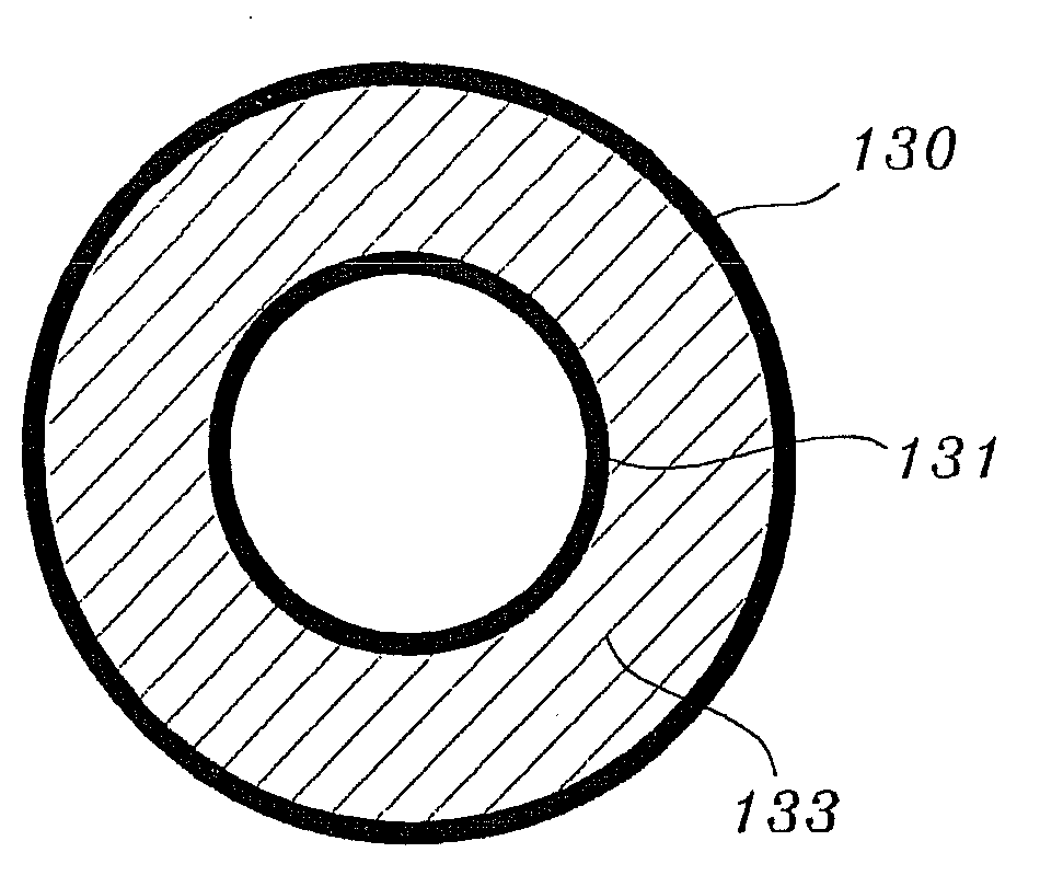
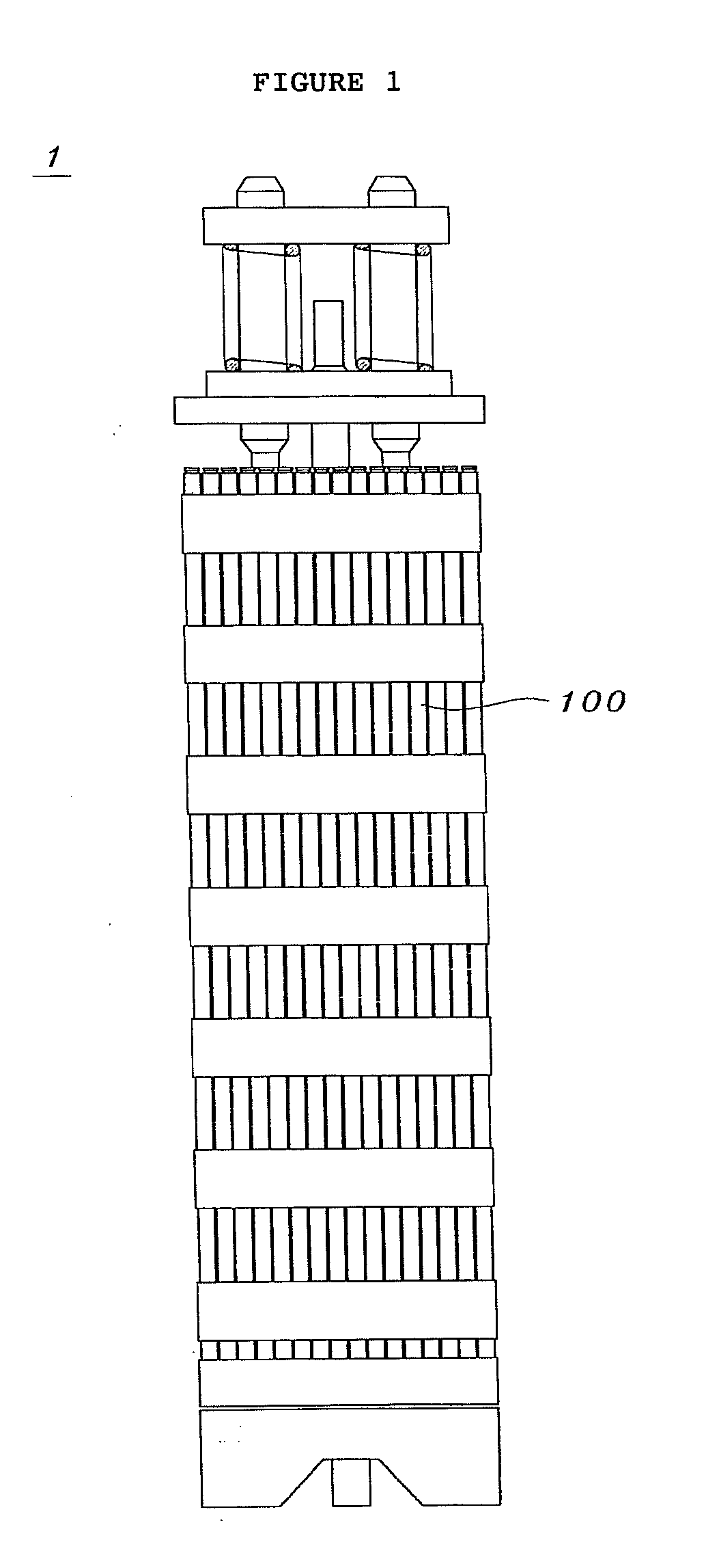
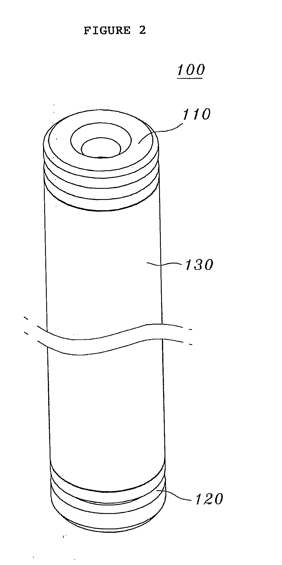
[0043]FIG. 1 illustrates a nuclear fuel assembly using a dual-cooled nuclear fuel rod having annular plugs according to an embodiment of the present invention. FIG. 2 is a perspective view illustrating a dual-cooled nuclear fuel rod having annular plugs according to an embodiment of the present invention. FIGS. 3 and 4 are cross-sectional views illustrating a dual-cooled nuclear fuel rod having annular plugs according to an embodiment of the present invention.

[0044]The dual-cooled nuclear fuel rod having annular plugs acco...


PUM

PropertyMeasurementUnit
Thicknessaaaaaaaaaa
Diameteraaaaaaaaaa
Circumferenceaaaaaaaaaa

Abstract

A dual-cooled nuclear fuel rod and a method of manufacturing the same are provided. The nuclear fuel rod includes an outer cladding tube having a circular cross section, an inner cladding tube having an outer diameter smaller than an inner diameter of the outer cladding tube, and a length longer than the outer cladding tube, and located in parallel in the outer cladding tube, a pellet charged in a space between the outer and inner cladding tubes and generating energy by nuclear fission, and first and second end plugs coupling opposite ends of the outer cladding tube to stepped outer joints formed on outer circumferences of first ends thereof and coupling opposite ends of the inner cladding tube to stepped inner joints formed on inner circumferences of the first ends thereof.

Description

CROSS-REFERENCES TO RELATED APPLICATION[0001]This patent application claims the benefit of priority under 35 U.S.C. §119 from Korean Patent Application No. 10-2009-0032747 filed on Apr. 15, 2009, the content of which is incorporated herein by reference.BACKGROUND OF THE INVENTION[0002]1. Field of the Invention[0003]The present invention relates, in general, to a dual-cooled nuclear fuel rod having annular plugs and method of manufacturing the same and, more particularly, to a dual-cooled nuclear fuel rod required to increase output of a standard pressurized light water atomic power plant on a large scale, and a method of manufacturing the dual-cooled nuclear fuel rod, capable of having direct application of welding of the dual-cooled nuclear fuel rod.[0004]2. Description of the Related Art[0005]Just as a fossil fuel such as oil or coal is needed to operate a thermoelectric power plant, nuclear fuel is needed to operate an atomic power plant. Here, as the requisite nuclear fuel, a nu...

Claims


Application Information

Patent Timeline
IPC IPC(8): G21C3/16C21D1/40
CPCG21C3/02Y02E30/40G21C21/02G21C3/10Y02E30/30G21C3/06
Inventor KIM, HYUNG-KYUKIM, JONG-HUNKIM, DAE-HOSONG, KUN-WOOYOON, KYUNG-HOLEE, YOUNG-HOKIM, JAE-YONGLEE, KANG-HEE
Owner KOREA ATOMIC ENERGY RES INST
Why Eureka
Try Eureka