System and Method for Pump with Deformable Bearing Surface

Active Publication Date: 2010-10-21
BOARD OF RGT THE UNIV OF TEXAS SYST
View PDF23 Cites 24 Cited by
  • Summary
  • Abstract
  • Description
  • Claims
  • Application Information

AI Technical Summary

Benefits of technology

[0038]Pumps similar to those disclosed in U.S. Pat. No. 6,576,010 are limited in that they aspirate and eject fluid at the same time. This feature has the disadvantage in that the inertia (inertance) of the fluid in both the inflow and outflow lines is coupled to the drive piston and must be accelerated each time a stroke is performed. This dynamic effect can generate significant pressures on the pistons, which requires additional power for actuation and can lead to pump malfunction or diminished performance if the pressures exceed actuation and coupling limits.
[0039]Furthermore, pumps similar to those disclosed in U.S. Pat. No. 6,576,010 are limited by the fact that when a piston crosses a port opening, it completely occludes the port area, which has the effect of rapidly increasing the resistance to flow through this area. If the fluid in the inflow or outflow lines have energy when the rapid increase in resistance occurs, a significant back pressure (fluid hammer) can arise which can generate pressures that make the pistons very hard to control. In order to prevent this fluid hammer, the energy of the fluid in the inflow and outflow lines should be significantly reduced before the port is occluded, which requires power and time. Reducing the energy of the fluid in the inflow and outflow lines also reduces pumping capability. In an application where the inflow or outflow inertances are large (e.g., long lines, dense fluid, small cross sectional flow area), this type of pump can suffer a significan

Problems solved by technology

Many natural and manmade fluids contain molecules that can be damaged or destroyed by excessive shearing strains or stagnation that can occur in devices that attempt to pump these fluids.
Fluids containing molecules with high molecular weights such as proteins, long stranded synthetic polymers, DNA, RNA, or fluids such as blood, which contain concentrations of delicate cells, are especially susceptible to being compromised by

Method used


Image

  • System and Method for Pump with Deformable Bearing Surface
  • System and Method for Pump with Deformable Bearing Surface
  • System and Method for Pump with Deformable Bearing Surface

Examples


Example

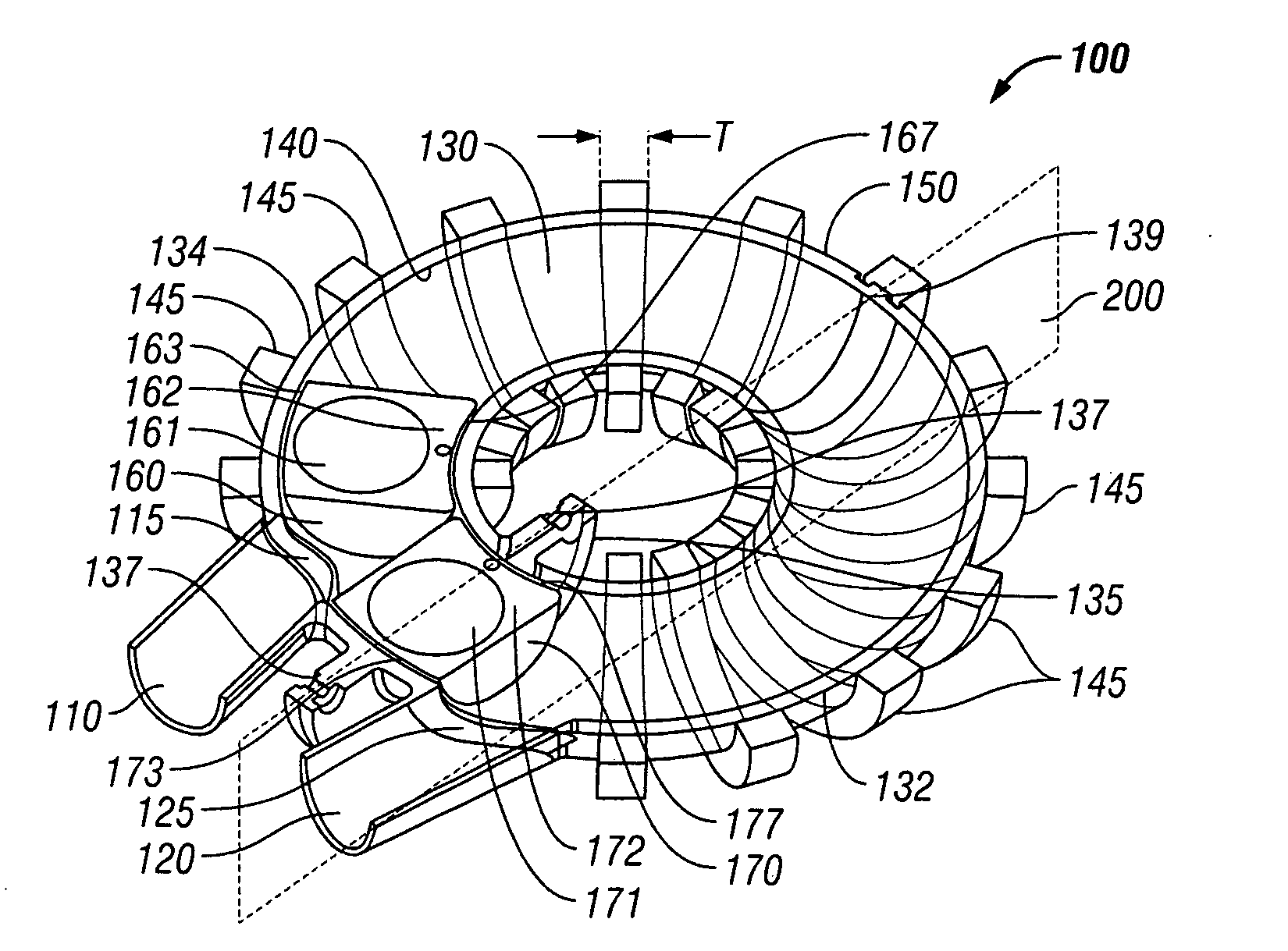
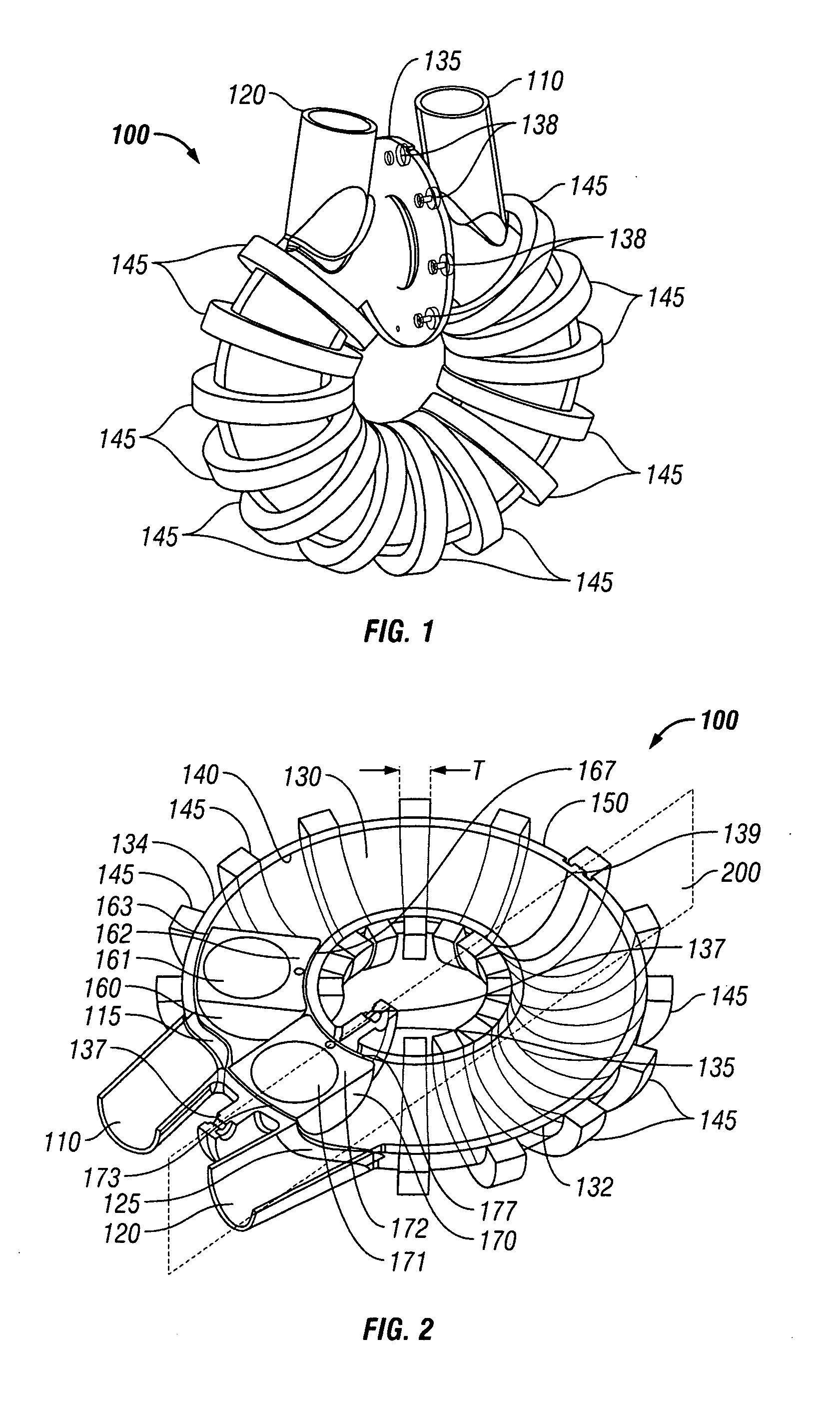
[0161]FIGS. 1 and 2 show a perspective and sectioned view, respectively, of a pump 100 with an inlet 110 and an outlet 120. It should be appreciated that pump 100 shown in FIGS. 1 and 2 is one exemplary embodiment, and the present invention should not be limited to the embodiment shown. The same is true for all other Figures, which are provided as examples only.

[0162]The embodiments illustrated in FIGS. 1-13 show a pumping chamber 130 forming a loop or ring comprised of an inner wall 140 and an outer wall 150 defining a lumen generated by the revolution of a two-dimensional enclosed contour, in this case a circle, about a coplanar axis lying outside the contour. It should be appreciated that many two dimensional enclosed contours can be used to define the lumen including a square, ellipse, polygon, conic, etc. It should also be appreciated that the revolution path should not be restricted to a circle. For instance, the enclosed contour may be swept around an oval, ellipse, etc. Pump...


PUM


Abstract

Systems and methods for pumping fluid comprising a pumping chamber, a pump inlet, a pump outlet, a valving mechanism, and a drive piston or pumping chamber wall including a deformable surface configured to provide elastohydrodynamic lubrication during operation.

Description

BACKGROUND OF THE INVENTION[0001]1. Field of the Invention[0002]Embodiments of the present invention generally relate to pumps. More specifically, and not by way of limitation, embodiments of the present invention relate to positive displacement pumps for the circulation of fluids.[0003]2. Description of Related Art[0004]Many natural and manmade fluids contain molecules that can be damaged or destroyed by excessive shearing strains or stagnation that can occur in devices that attempt to pump these fluids. Fluids containing molecules with high molecular weights such as proteins, long stranded synthetic polymers, DNA, RNA, or fluids such as blood, which contain concentrations of delicate cells, are especially susceptible to being compromised by many conventional pumping techniques.[0005]Typical axial flow and centrifugal pumps operate by rotating an impeller at very high speeds, often exceeding 12,000 RPM. The shearing stresses that can arise at these velocities can strain larger flui...

Claims


Application Information

Patent Timeline
IPC IPC(8): F04B17/04
CPCF04B17/04F04B49/00
Inventor GOHEAN, JEFFREY R.PATE, THOMAS D.LONGORIA, RAUL G.SMALLING, RICHARD
Owner BOARD OF RGT THE UNIV OF TEXAS SYST
Why Eureka
Try Eureka