Blood clot prevention device

a blood clot and cuff technology, applied in contraceptive devices, artificial respiration, therapy, etc., can solve the problems of dvt, serious illness or even death, and potentially fatal blood clot formation, so as to prevent the formation of blood clots, stimulate blood flow, and save power

Active Publication Date: 2010-10-21
KHAN SITARA R
View PDF15 Cites 65 Cited by
  • Summary
  • Abstract
  • Description
  • Claims
  • Application Information

AI Technical Summary

Benefits of technology

[0007]In order to stimulate blood flow and prevent the formation of blood clots, a pressure cuff containing a series of bladders is worn on the arm or leg of a user and is adjustable to fit different users at different points of the arm or leg, e.g., by using a hook and latch fastener, a hook and loop fastener, or any other type of fastener that can secure the cuff to a user. Each of the bladders is connected to an air compressor by a tube containing a valve. The air compressor and valves are operated by a control module powered by a power source. The control module runs the air compressor and opens the valves in succession to pressurize the bladders one after another along the arm or leg of a user. Different pressure levels and different dwell limes are contemplated and more than one bladder may be pre

Problems solved by technology

While several factors, such as advanced age, a persons weight, and other health characteristics may increase or decrease the likelihood of DVT occurring, extended periods of immobility, are a likely cause of DVT occurring in the legs.
If a person does suffer from DVT, a potentially fatal blood clot could form which may be large enough that

Method used


Image

  • Blood clot prevention device
  • Blood clot prevention device
  • Blood clot prevention device

Examples


Embodiment Construction

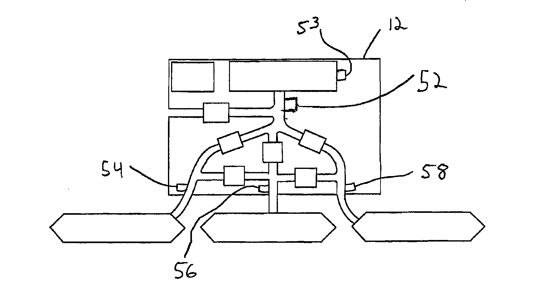
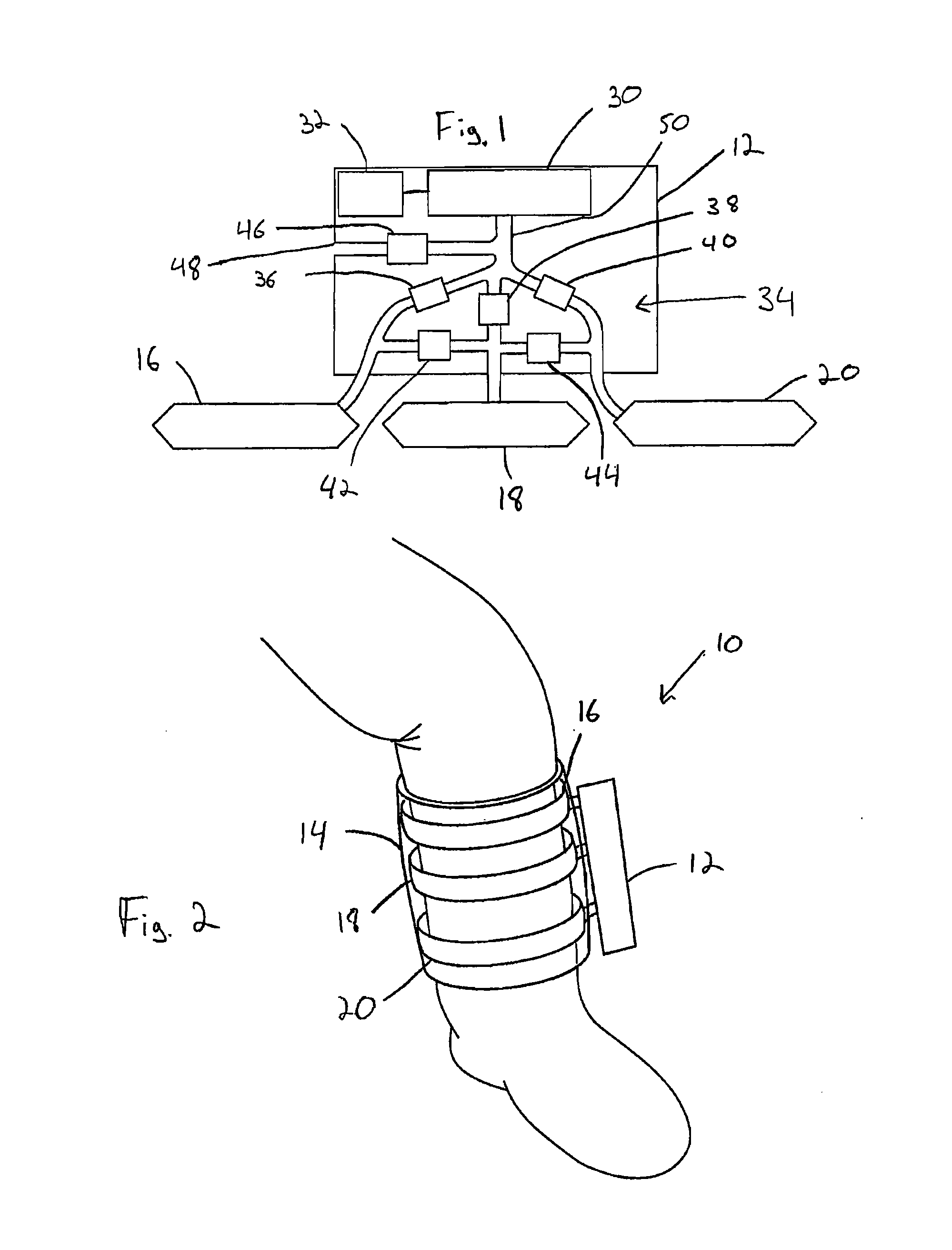
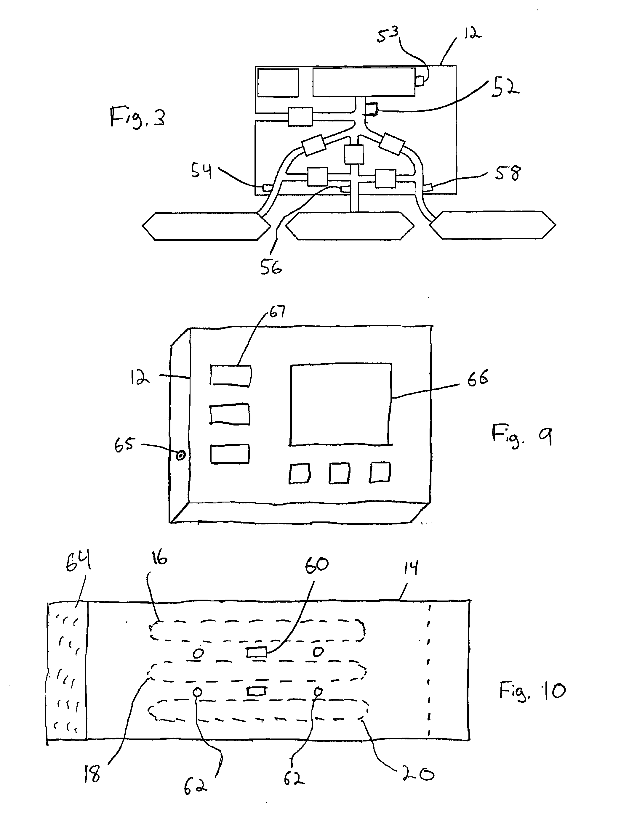
[0017]Referring now to FIGS. 1 and 2, the pressure cuff device 10 for the prevention of the formation of blood clots comprises a pressure cuff control unit 12 and a cuff 14 attached thereto. The cuff 14 is sized so as to fit around the calf area of the leg of a user. Within the cuff 14 are disposed three or more pressure bladders 16, 18, and 20. Thus FIG. 1 shows a cuff having three bladders, alternative embodiments may include any number of bladders. The three pressure bladders 16, 18, and 20 extend substantially around the circumference of the user's leg and are arranged along the length of the user's leg. The bladders can also be dimensioned and positioned within the cuff 14 such that the bladders only extend around approximately two-thirds of the circumference of the back portion of the user's leg, for example as shown in FIG. 13. Thus, the bladders will be positioned to inflate and press against the muscular calf portion of the user's leg, and not the shin bone located in the f...


PUM


Abstract

An adjustable pressure cuff device is provided for the arm or leg of a user for stimulating blood flow and preventing blood clots. The pressure cuff contains a number of bladders which wrap in the direction of the cuff and which are arranged in succession down the arm or leg of a user. An air compressor is connected to the bladders via a multiplicity of tubes, each of which contain a valve. A control module runs the air compressor and sequentially opens the valves to provide air pressure to the bladders in succession along the arm or leg of a user. Further, between the bladders and the valves, additional tubes containing valves are provided to equalize pressure between bladders before exhausting the air from a previously pressurized bladder to save power and allow for increased patterns of bladder pressure. The pressure levels and bladder dwell times may be adjusted by the user or based on predetermined settings. Optionally, the device provides electrical stimulation, pulsations, heating, and cooling.

Description

CROSS REFERENCE TO RELATED APPLICATIONS[0001]This application claims priority to U.S. Provisional Application Ser. No. 60 / 978,730, filed Oct. 9, 2007, entitled “Blood Clot Prevention Device.” The contents of which are incorporated herein by reference in its entirety.FIELD OF THE INVENTION[0002]The present invention generally relates to pressure cuffs, and more specifically to a pressure cuff with multiple pressure bladders.BACKGROUND[0003]There appears to be a link between extended periods of immobility in confined quarters, such as a person might experience on a long journey in an airplane or other vehicle, and the occurrence of Deep Vein Thrombosis (DVT) or the formation of blood clots in the lower extremities of an individual. Further, extended periods of immobility may aggravate other conditions such as arthritis, various neuropathies, swelling, lymphedema, fibromyalgia, tension headaches, and other bone and muscle injuries.[0004]While several factors, such as advanced age, a pe...

Claims


Application Information

Patent Timeline
IPC IPC(8): A61H7/00A61H1/00A61N1/36A61F7/08A61F7/10
CPCA61H9/0078A61N1/00A61H2201/0103A61H2201/0176A61H2201/0207A61H2201/0214A61H2201/0242A61H2201/10A61H2201/165A61H2201/5043A61H2201/5071A61H2201/5082A61H2201/5097A61H2205/06A61H2205/062A61H2205/10A61H2205/102A61H23/02
Inventor KHAN, SITARA R.
Owner KHAN SITARA R
Why Eureka
Try Eureka