Hydrodynamic torque converter

a technology of torque converter and torsional vibration, which is applied in the direction of fluid gearing, coupling, belt/chain/gearing, etc., can solve the problems of less suitable and costly devices for torsional vibration damping, and achieve the effect of cost-effective manufacturing and increased insulation capacity of torsional vibration

Active Publication Date: 2010-10-28
SCHAEFFLER TECH AG & CO KG
View PDF8 Cites 111 Cited by
  • Summary
  • Abstract
  • Description
  • Claims
  • Application Information

AI Technical Summary

Benefits of technology

[0005]The task arises therefore to propose a turbine damper that despite little assembly space requiremen

Problems solved by technology

Particularly, for compact assembly space requirements, such devices for torsional vibratio

Method used


Image

  • Hydrodynamic torque converter
  • Hydrodynamic torque converter
  • Hydrodynamic torque converter

Examples


Embodiment Construction

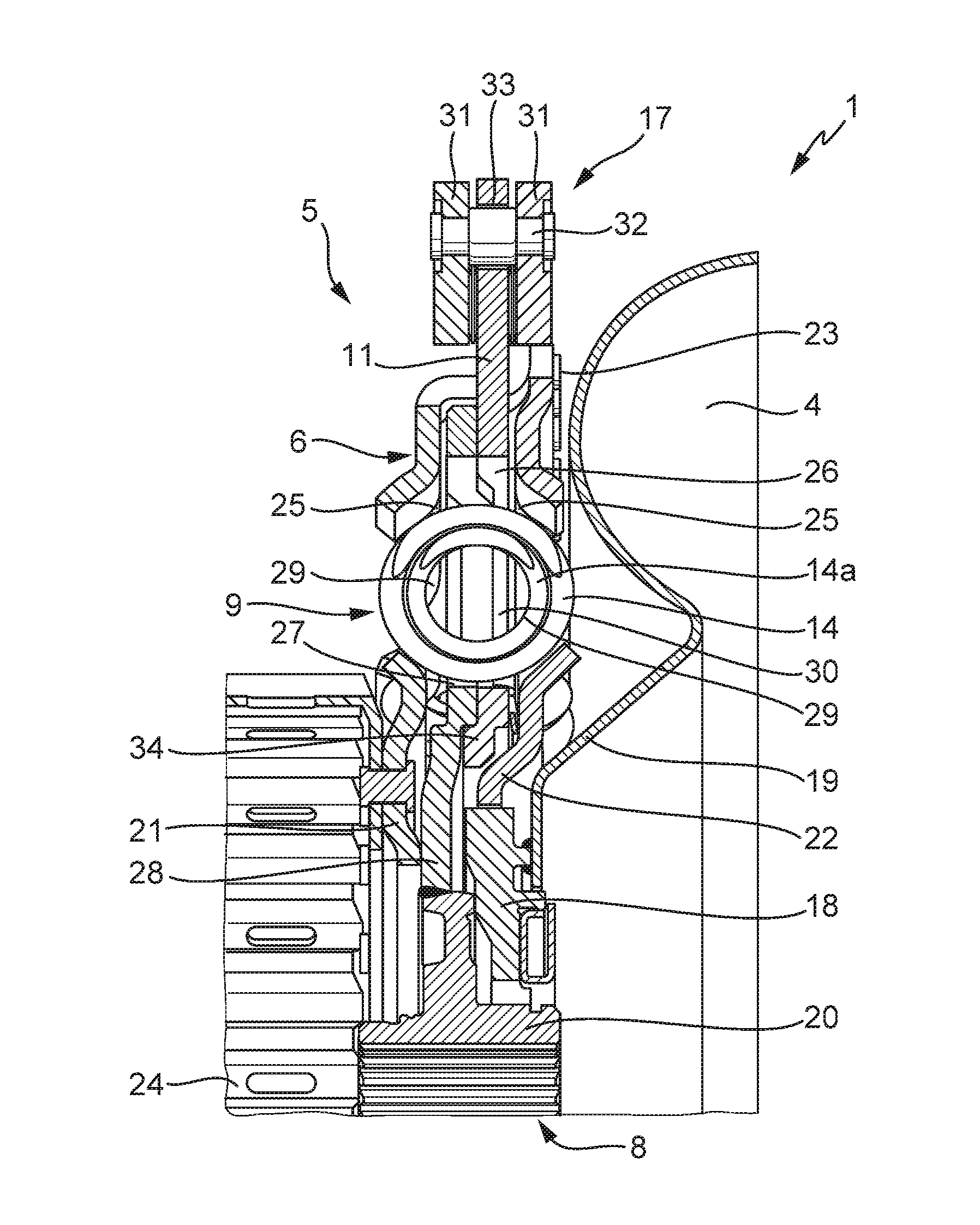
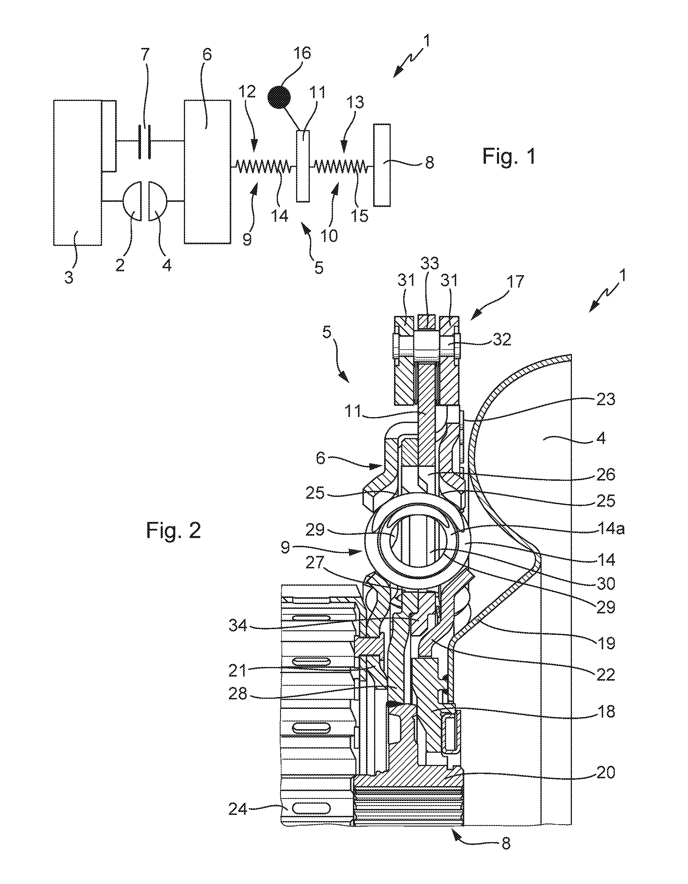
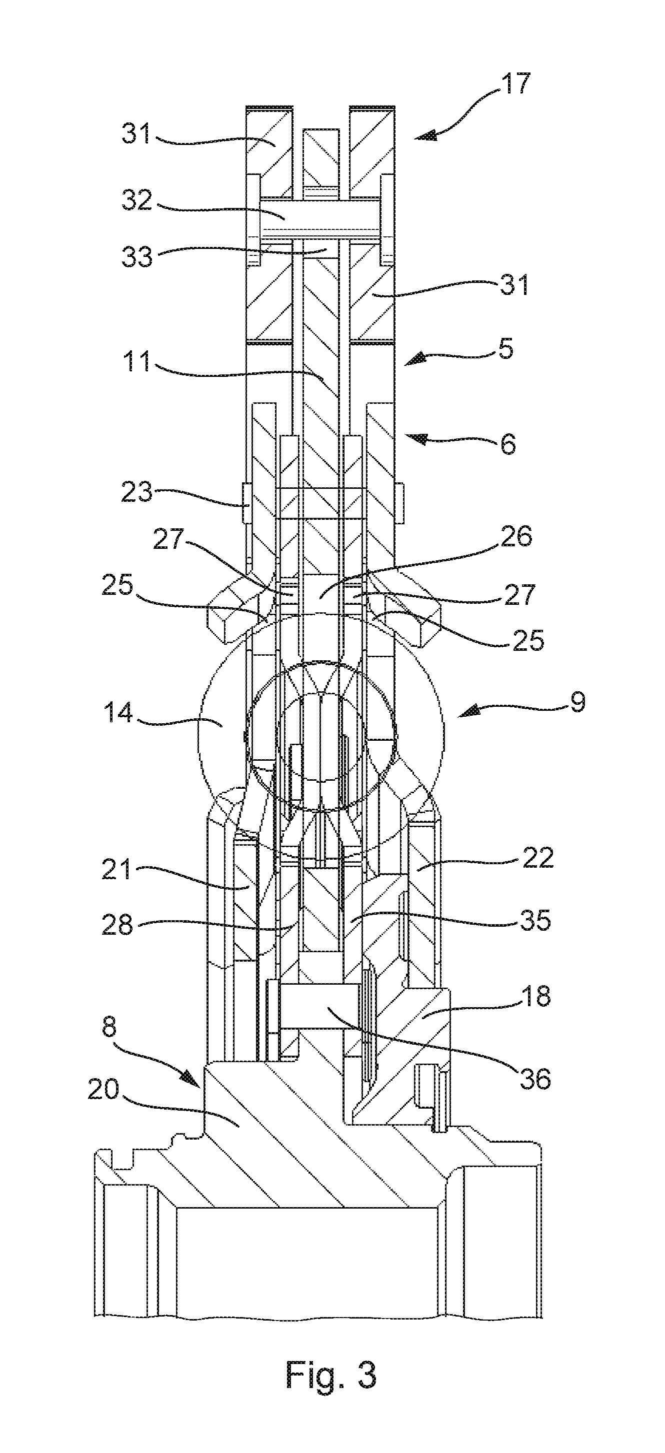
[0017]FIG. 1 shows a principal diagram of hydrodynamic torque converter 1. Impeller 2 that can be a component part of housing 3 driven by an internal combustion engine—not depicted—which drives turbine 4 that is connected with input part 6 of turbine damper 5. At the same time, lock-up clutch 7 is connected with input part 6, which bypasses impeller 2 and turbine 4 in the closed state.

[0018]Output part 8 of turbine damper 5 is connected with a non-depicted transmission input shaft of a transmission. Turbine damper 5 is designed as series-connected turbine damper 5 with two damper parts 9, 10, wherein intermediate flange 11 separates two damper parts 9, 10 from one another. Damper parts 9, 10 contain, respectively, first and second energy accumulator 12, 13, which are formed respectively by coil springs 14, 15. Intermediate flange 11 contains adaptive-speed vibration absorber 16.

[0019]Due to the serial arrangement of damper parts 9, 10 inside turbine damper 5, a low spring rate can b...


PUM


Abstract

The invention relates to a hydrodynamic torque converter with an impeller connected on the drive side arranged in housing and a turbine driven by the latter, connected with the driven side of the torque converter, with a turbine damper actively disposed between the turbine and driven side. To improve the vibration damping on the driven side of the torque converter, it is proposed the turbine damper with a first damper part formed out of an input part connected with the turbine and an intermediate flange, limited and rotatable opposite and against the action of at least a first energy accumulator and a second damper part with the intermediate flange and an output part limited and rotatable oppositely and against the action of at least a second energy accumulator, wherein an adaptive-speed vibration absorber is arranged on the intermediate flange.

Description

CROSS-REFERENCE TO RELATED APPLICATIONS[0001]This application claims priority from German Patent Application No. DE 10 2009 018 753.7, filed Apr. 27, 2009, which application is incorporated herein by reference in its entirety.FIELD OF THE INVENTION[0002]The invention relates to a hydrodynamic torque converter with an impeller connected on the drive side and arranged in housing, a turbine driven by said impeller, connected with a driven side of the torque converter as well as a turbine damper disposed to act between the turbine and the driven side.BACKGROUND OF THE INVENTION[0003]Hydrodynamic torque converters with turbine dampers are known. In that case, a torsional vibration damper is actively disposed between the turbine shell and the driven side of the torque converter, in that, for instance, the turbine hub accommodating the turbine shell is rotatably connected on the driven side, for instance, on a converter hub, which is connected rotatably by means of input splined shaft of t...

Claims


Application Information

Patent Timeline
IPC IPC(8): F16D33/00
CPCF16F15/145F16H2045/0263F16H2045/0247F16H2045/007
Inventor ENGELMANN, DOMINIQUEWERNER, MARKUSMAIENSCHEIN, STEPHANDINGER, CHRISTIAN
Owner SCHAEFFLER TECH AG & CO KG
Why Eureka
Try Eureka