[0015]If the
precondition for performing the malfunction diagnosis is satisfied when the process of starting the engine is started, the time point, at which the current process of starting the engine is started is not immediately after the time point at which the process of stopping the engine is completed, and the engine has been stopped for a long period so that the
coolant temperature and the intake air temperature have become substantially equal to the
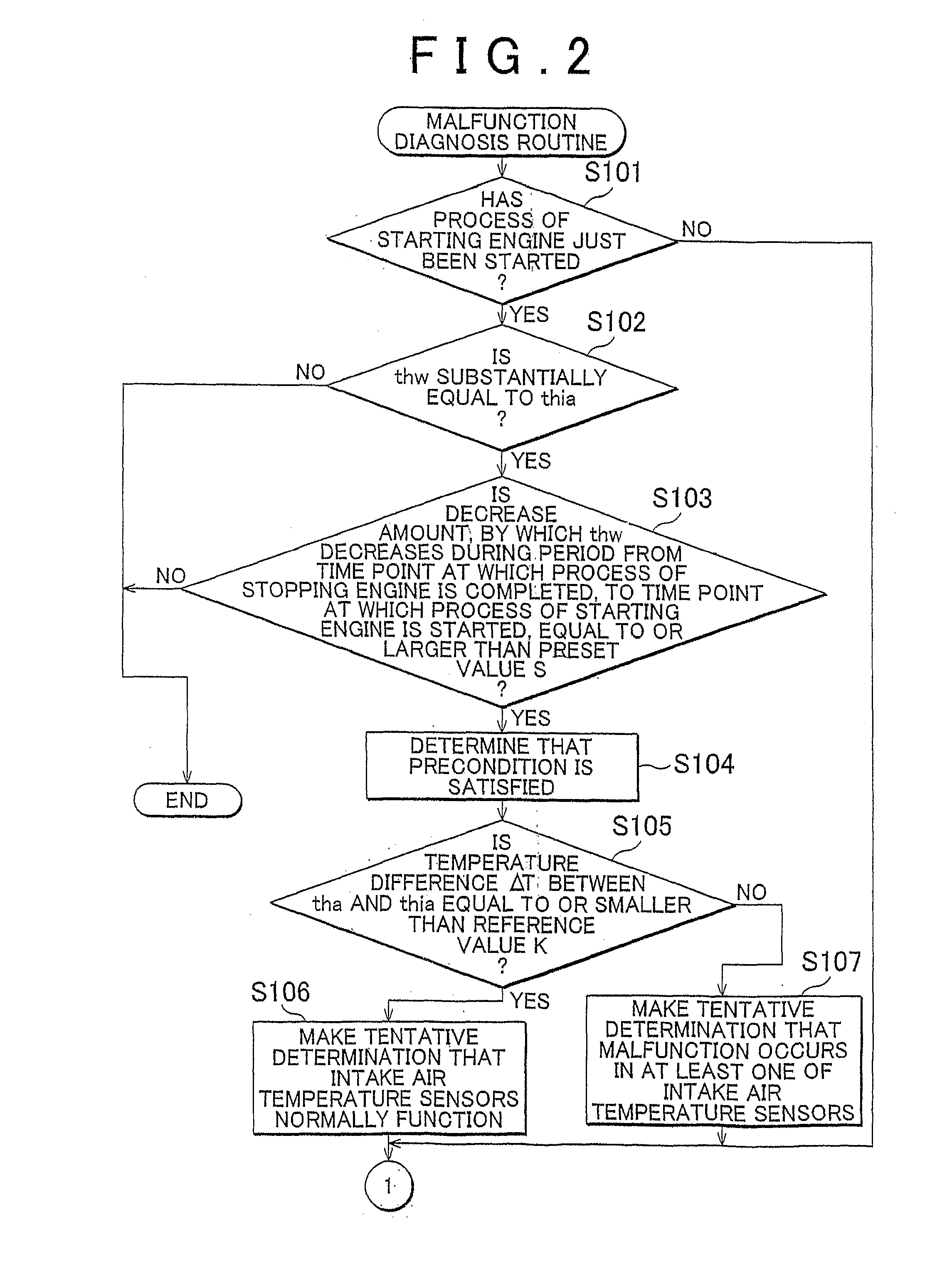
outside air temperature. If the above-described precondition is satisfied when the process of starting the engine is started, a tentative determination that a malfunction occurs in at least one of the first and second intake air temperature sensors is made, based on the fact that the difference between the intake air temperatures detected by the first and second intake air temperature sensors is larger than the reference value that is set in advance. Because the tentative determination, that a malfunction occurs in at least one of the first and second intake air temperature sensors, is made based on the
temperature difference between the intake air temperatures detected by the first and second intake air temperature sensors, there is a possibility that a malfunction occurs in the first and second intake air temperatures when the tentative determination is made. Also, the tentative determination, that a malfunction occurs in at least one of the first and second intake air temperature sensors, is made, on the assumption that the process of starting the engine has just been started, and the intake air temperature is not influenced by heat generated by the engine. This avoids the situation where it is not possible to make an accurate tentative determination that a malfunction occurs in at least one of the first and second intake air temperature sensors, due to the influence of, for example, a change in the amount of heat generated by the engine.
[0018]Thus, it is possible to make an accurate determination that a Malfunction occurs in at least one of the first and second intake air temperature sensors, or an accurate determination that the first and second intake air temperature sensors normally function. That is, it is possible to accurately determine whether a malfunction occurs in the first and second intake air temperature sensors.
[0020]With the above-described configuration, to determine whether the tentative determination that a malfunction occurs in at least one of the first and second intake air temperature sensors (or the tentative determination that the first and second intake air temperature sensors normally function) is an invalid determination or a valid determination, it is determined whether at least one of the intake air temperatures detected by the first and second intake air temperature sensors changes during the time period from the time point at which the process of starting the engine is started and the cumulative amount of intake air for the engine is “0”, to the time point at which the cumulative amount becomes equal to or larger than the predetermined value. The above-described time period is shorter than the time period from the time point at which the process of starting the engine is started, to the time point at which the heat generated by the engine is transmitted to the air in the intake passage. Also, the above-described time period is longer than a time period required to deliver, to the
combustion chambers, all the air that exists in the intake passage at the time point at which the process of starting the engine is started. Accordingly, if at least one of the intake air temperatures detected by the first and second intake air temperature sensors changes during the above-described time period, it is possible to appropriately determine that the change in the intake air temperature is caused by, for example, the solar
radiation received at the portion of the vehicle, which is close to at least one intake air temperature sensor. Accordingly, the tentative determination that a malfunction occurs in at least one of the first and second intake air temperature sensors, or the tentative determination that the first and second intake air temperature sensors normally function, is appropriately determined to be an invalid determination. On the other hand, if neither of the intake air temperatures detected by the first and second intake air temperature sensors changes during the above-described time period, it is possible to appropriately determine that the first and second intake air temperature sensors are not influenced by the solar
radiation and the like. Accordingly, the tentative determination that a malfunction occurs in at least one of the first and second intake air temperature sensors, or the tentative determination that the first and second intake air temperature sensors normally function, is appropriately determined to be a valid determination. Thus, when it is determined whether a malfunction occurs in the first and second intake air temperature sensors, it is possible to appropriately eliminate the influence of the solar
radiation and the like. Accordingly, it is possible to make an accurate determination that a malfunction occurs in at least one of the first and second intake air temperature sensors, or an accurate determination that the first and second intake air temperature sensors normally function.
[0023]However, with the above-described configuration, the second condition needs to be satisfied to satisfy the precondition. Further, the preset value used in the second condition is equivalent to the decrease amount by which the
coolant temperature decreases during a time period longer than the time period from the time point at which the process of stopping the
internal combustion engine is completed, to a time point at which each of the intake air temperatures becomes lower than a value near the highest value after an increase of each of the intake air temperatures to the highest value. Therefore, in the case where the precondition is satisfied, the intake air temperature has become lower than a value near the highest value after completion of the process of stopping the engine and the second determination portion tentatively determines whether a malfunction occurs in the first and second intake air temperature sensors. This avoids the situation where the tentative determination is made while the intake air temperature is unstable. Thus, it is possible to avoid the situation where the tentative determination that a malfunction occurs in at least one of the first and second intake air temperature sensors, or the tentative determination that the first and second intake air temperature sensors normally function, is an inaccurate determination.
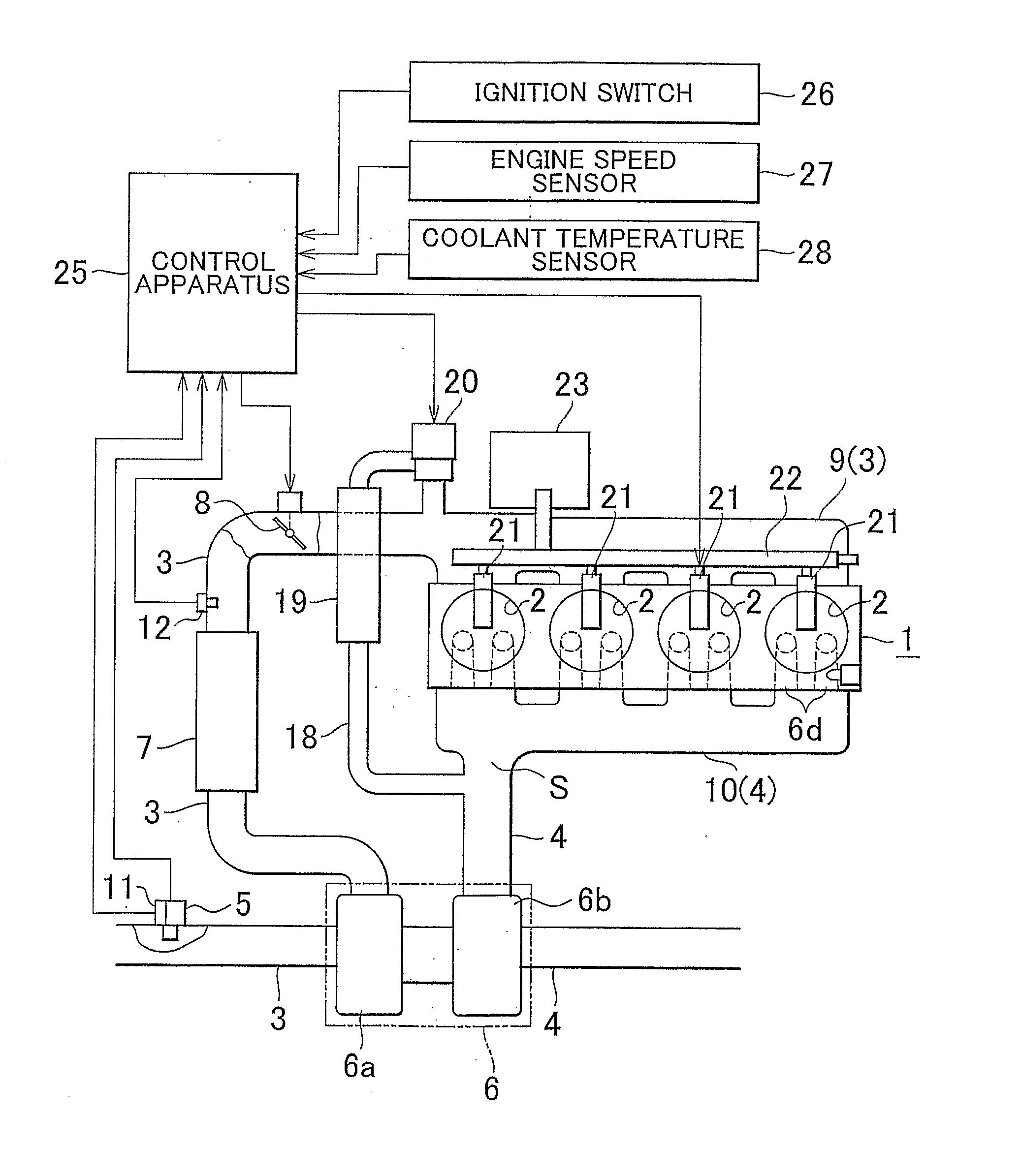
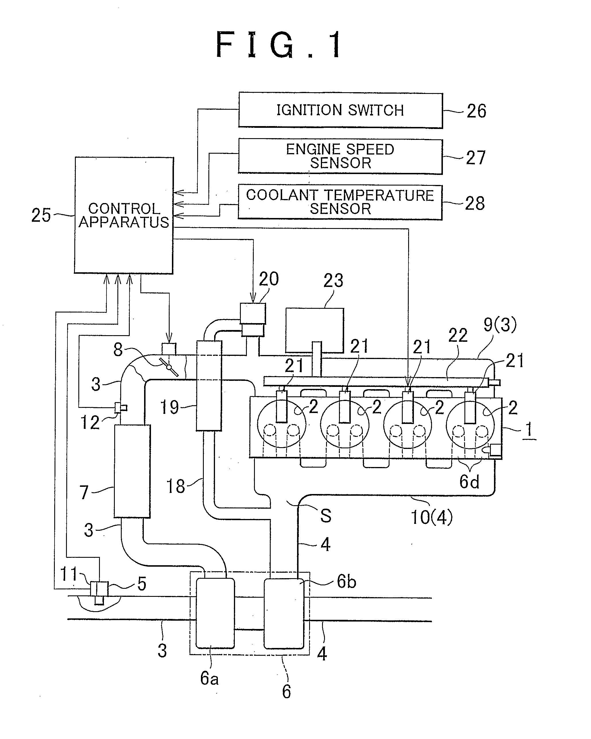
[0026]If the intake air temperatures detected by the first and second intake air temperature sensors differ from each other in the situation where the precondition is satisfied when the process of starting the
internal combustion engine is started, the intake air temperature, which is detected by the first intake air temperature sensor provided in a portion of the intake passage, which is less likely to be cooled, that is, the intake air temperature used for the EGR control may deviate from an appropriate value (i.e., an actual intake air temperature). However, if the difference between the intake air temperature detected by the first intake air temperature sensor and the appropriate value is equal to or smaller than the reference value, the level of deterioration of exhaust emissions from the internal
combustion engine, which is caused by the deviation, does not exceed the allowable limit level. In this case, the second determination portion tentatively determines that the first and second intake air temperature sensors normally function. That is, the second determination portion does not make the tentative determination that a malfunction occurs in at least one of the first and second intake air temperature sensors. In the above-described situation, the difference between the intake air temperatures detected by the first and second intake air temperature sensors may become larger than the reference value. In this case, the deviation of the intake air temperature detected by the first intake air temperature sensor provided in the portion of the intake passage which is less likely to be cooled, from the appropriate value may be larger than the reference value, and the level of deterioration of exhaust emissions from the internal
combustion engine, which is caused by the deviation, may exceed the allowable limit level. In this case, the second determination portion makes the tentative determination that a malfunction occurs in at least one of the first and second intake air temperature sensors. Thus, if a malfunction, which makes the level of deterioration of exhaust emissions from the engine exceed the allowable limit level, occurs in the first intake air temperature sensor, it is possible to accurately make the tentative determination that a malfunction occurs in at least one of the first and second intake air temperature sensors. If such a serious malfunction does not occur in the first intake air temperature sensor, it is possible to accurately make the tentative determination that the first and second intake air temperature sensors normally function. This avoids the situation where a tentative determination that a malfunction occurs in at least one of the first and second intake air temperature sensors is made according to an extremely strict criterion.

