Lifetime optimization of a wind turbine generator by controlling the generator temperature

a technology of generator temperature and life-time optimization, which is applied in the direction of engine control, motors, engine fuctions, etc., can solve the problems of reducing the power affecting the efficiency of wind turbine generators, so as to reduce the amount of power.

Active Publication Date: 2010-10-28
VESTAS WIND SYST AS
View PDF4 Cites 46 Cited by
  • Summary
  • Abstract
  • Description
  • Claims
  • Application Information

AI Technical Summary

Benefits of technology

[0056]Rotating the wind turbine slightly away from the wind direction reduces the amount of power that the wind turbine has to handle and, thus, the thermal load on the generator and other parts of the wind turbine.

Problems solved by technology

Thermal stress to components containing or comprising materials of different thermal expansion coefficients is a well-known problem.
Within the art of making wind turbines, this problem is particularly pronounced due to the very varying operational and climatic conditions, that many wind turbines are exposed to.
Especially electric components, such as the generators of wind turbines, are vulnerable to thermal stress.
Overheating of the windings of a generator does not only reduce the lifetime of the windings due to chemical decomposition of the insulating materials but can also lead to more immediate damage to or even destruction of the windings.
Even more important, varying temperatures result in consecutive extensions and contractions of the mechanical parts of the electrical components, which can eventually lead to fatigue of the materials constituting the parts and, thereby, damage to or destruction of the electrical components.
Furthermore, the lifetime of generator windings is reduced because different thermal expansion coefficients of the conducting material, the insulating material and the material surrounding the windings result in decomposition due to mechanical wear of the different materials as they slide against each other, because they expand differently when the temperature changes.
If lubricants are used at temperatures outside the temperature ranges, within which they are made to work optimally, the friction between different lubricated materials as they slide against each other, because they expand differently when the temperature changes and, thereby, the mechanical wear of the materials may be increased.
If this should be accomplished by a heating and cooling system, however, the capacity of this system should be extremely high, and the system would be very expensive in manufacturing and operation as well as in maintenance costs.
Furthermore, such a heating and cooling system would be both large and heavy, which is particularly disadvantageous in the field of wind turbines.
The use of temperature sensors of this type, however, is not very useful for monitoring the rotor temperature because the rotation of the rotor complicates the transmission of the sensor output to a control system.
Normally, measurement signals are transmitted from the rotor to the stationary part of the generator through a system of slip rings, but the electrical resistances of such a slip ring system are not constant.
In fact, the variations of the slip ring resistances may, in severe cases, exceed the variations of the resistances of the temperature dependent resistors which makes the use of slip rings unsuitable for rotor temperature monitoring.
Generally, direct rotor temperature monitoring is usually not performed in wind turbine generators and, thus, there is a risk of overheating the rotor windings of the generator.
Especially so, because the power in the rotor windings varies during operation of the wind turbine, which makes the variations of the temperature in the rotor difficult to predict if it is not being monitored.
There are at least two major problems related to the commonly used control strategy associated with the above-mentioned monitoring of a series of parameters.
Firstly, the strategy normally consists of derating the power production of the wind turbine, whenever a certain safety limit of a monitored value is reached.
This leads to a non-optimized power production, since the production is derated if only one of the monitored parameters is at a critical level, although the actual generator temperature may be far from critical.

Method used


Image

  • Lifetime optimization of a wind turbine generator by controlling the generator temperature
  • Lifetime optimization of a wind turbine generator by controlling the generator temperature
  • Lifetime optimization of a wind turbine generator by controlling the generator temperature

Examples


Embodiment Construction

[0082]In the following is disclosed some embodiments of the present invention.

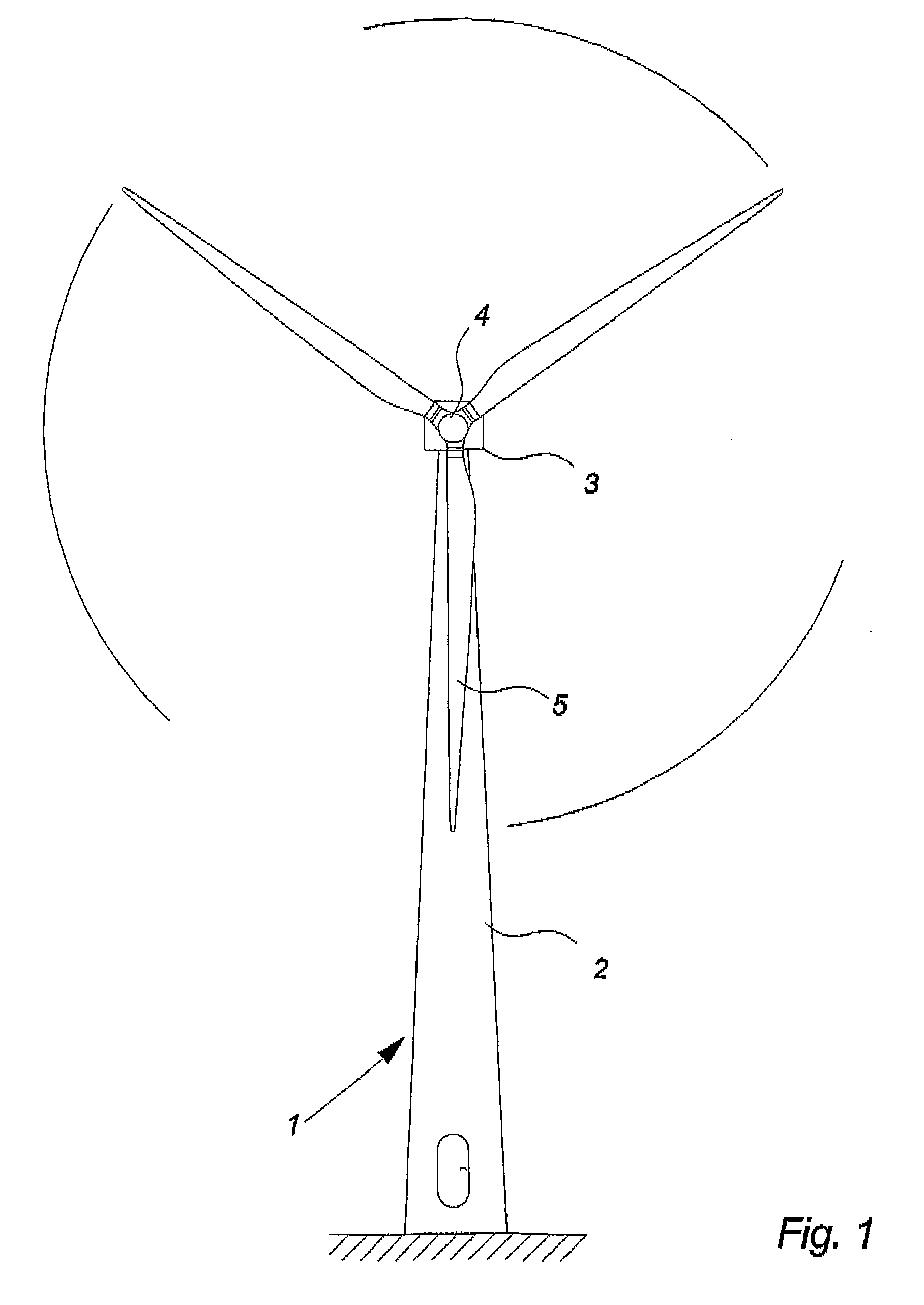
[0083]FIG. 1 illustrates a modern wind turbine 1, comprising a tower 2 and a wind turbine nacelle 3 positioned on top of the tower 2. The wind turbine rotor 4 comprising three wind turbine blades 5 is connected to the nacelle 3 through a low speed shaft (not shown) which extends from the front of the nacelle 3.

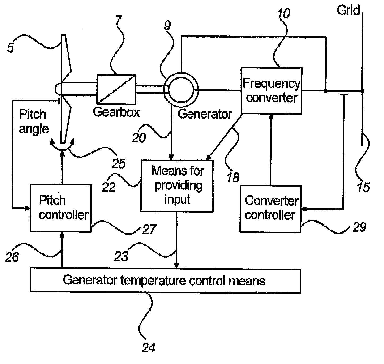
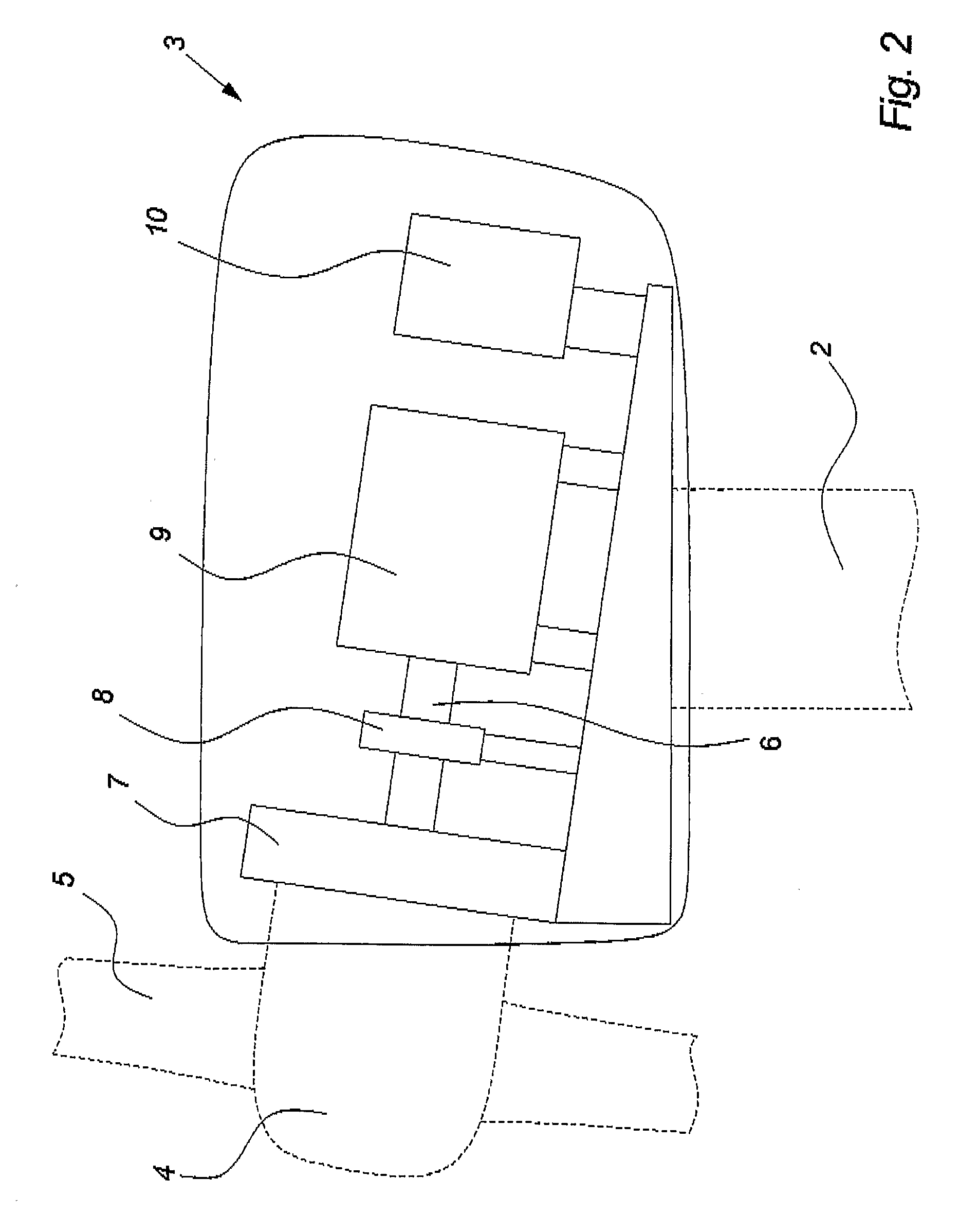
[0084]FIG. 2 illustrates a simplified cross section of a wind turbine nacelle 3, as seen from the side. In the shown embodiment, the drive train 6 in the nacelle 3 comprises a gear 7, a breaking system 8, a generator 9 and a frequency converter 10. It should be noted that not all wind turbine drive trains 6 include all of the components 7-10 shown in the figure. Depending on the type of generator 9 used in the wind turbine 1, the gear 7 and / or the frequency converter 10 may be absent.

[0085]An example of a generator 9 which is connected to a utility grid 15 partly through a frequency converter 10 is a...


PUM


Abstract

A wind turbine and a method for controlling the temperature of a wind turbine generator are disclosed, the wind turbine comprising a generator, generator temperature control means and means for providing input representative of at least one temperature of the generator to the generator temperature control means, the generator temperature control means including a closed-loop regulation arranged to determine a deviation of the input from at least one desired value, compute the magnitude of at least one control output in dependency of the determined deviation, and feed the control output to at least one controller of the wind turbine in order to reduce the deviation, the controller comprising control means for controlling the operation of the wind turbine in response to the at least one control output by changing one or more operational parameters of the wind turbine, which parameters influence the at least one temperature of the generator.

Description

[0001]The present invention relates to a variable speed wind turbine comprising a generator.BACKGROUND[0002]Thermal stress to components containing or comprising materials of different thermal expansion coefficients is a well-known problem. Within the art of making wind turbines, this problem is particularly pronounced due to the very varying operational and climatic conditions, that many wind turbines are exposed to. Especially electric components, such as the generators of wind turbines, are vulnerable to thermal stress.[0003]Basically, thermal stress originates from two factors, namely high temperatures and, more important, varying temperatures.[0004]Overheating of the windings of a generator does not only reduce the lifetime of the windings due to chemical decomposition of the insulating materials but can also lead to more immediate damage to or even destruction of the windings.[0005]The lifetime of the insulating material depends strongly on the temperature of the material, and...

Claims


Application Information

Patent Timeline
Patent Type & Authority Applications(United States)
IPC IPC(8): H02P9/04
CPCF03D7/0224F03D7/044F05B2220/704F05B2260/80F05B2260/821H02P2101/15F05B2270/3032H02P9/04H02P9/14Y02E10/723H02P2009/004F05B2270/303Y02E10/72
Inventor POULSEN, BORGERIMMEN, PETER DE PLACE
Owner VESTAS WIND SYST AS
Why Eureka
Try Eureka