Piezo devices with air-spaced cantilever

a composite cantilever and piezoelectric technology, applied in the field of piezoelectric devices, can solve the problems of small signal-to-noise ratio and limited sensitivity of piezoelectric devices, and achieve the effects of increasing the distance between the piezoelectric layer and the neutral plane, increasing the voltage generated as a result of vibration, and increasing the energy conversion efficiency

Active Publication Date: 2010-10-28
WAYNE STATE UNIV
View PDF5 Cites 32 Cited by
  • Summary
  • Abstract
  • Description
  • Claims
  • Application Information

AI Technical Summary

Benefits of technology

[0009]The foregoing and other objects are achieved by this invention, which provides, piezo devices having air-spaced piezoelectric cantilevers. The voltage that is generated as a result of vibrations is significantly increased since the distance between the piezoelectric layer and the neutral plane is increased. In addition,

Problems solved by technology

Since of the distance between the active layer and neutral plane is small in such known devices, their sensitivity is limited.
In addition, an unacc

Method used


Image

  • Piezo devices with air-spaced cantilever
  • Piezo devices with air-spaced cantilever
  • Piezo devices with air-spaced cantilever

Examples


Embodiment Construction

Vibration Energy Harvesting Device with Air-Spaced Piezoelectric Cantilevers

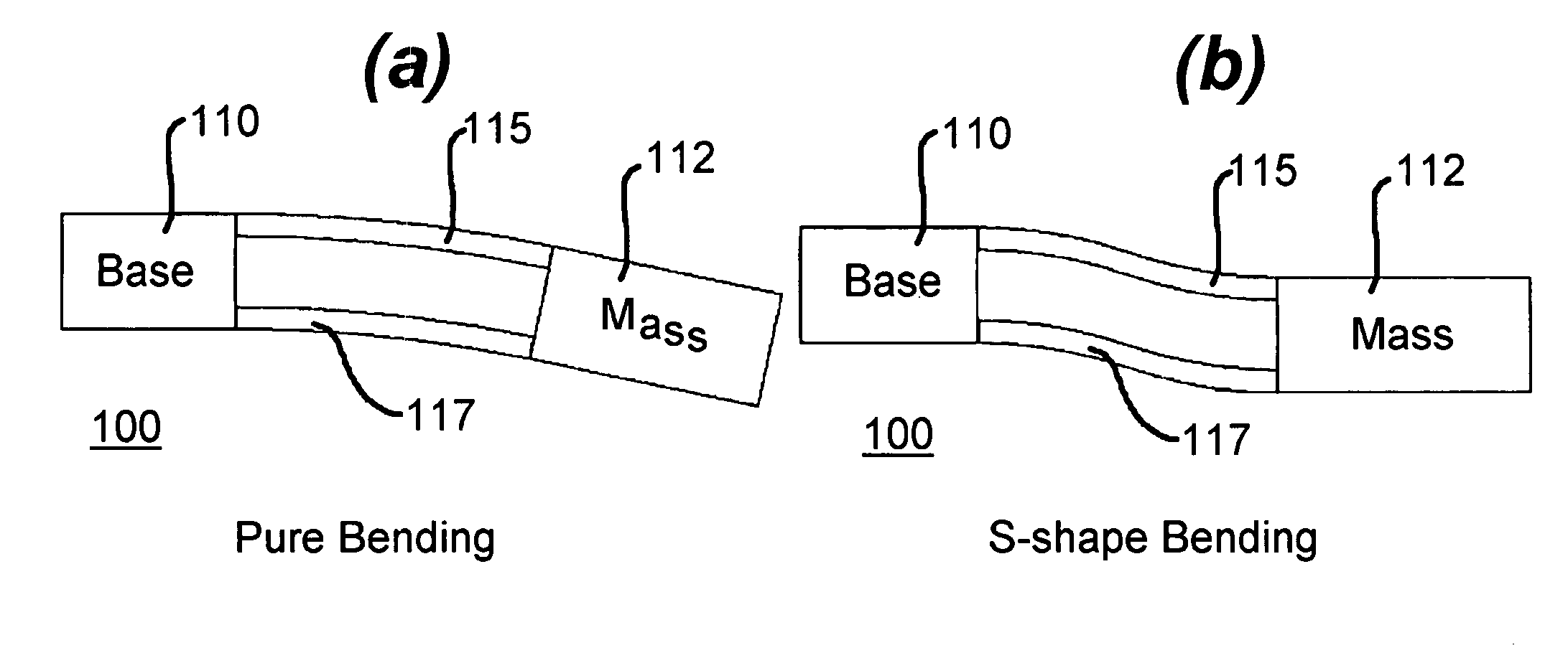
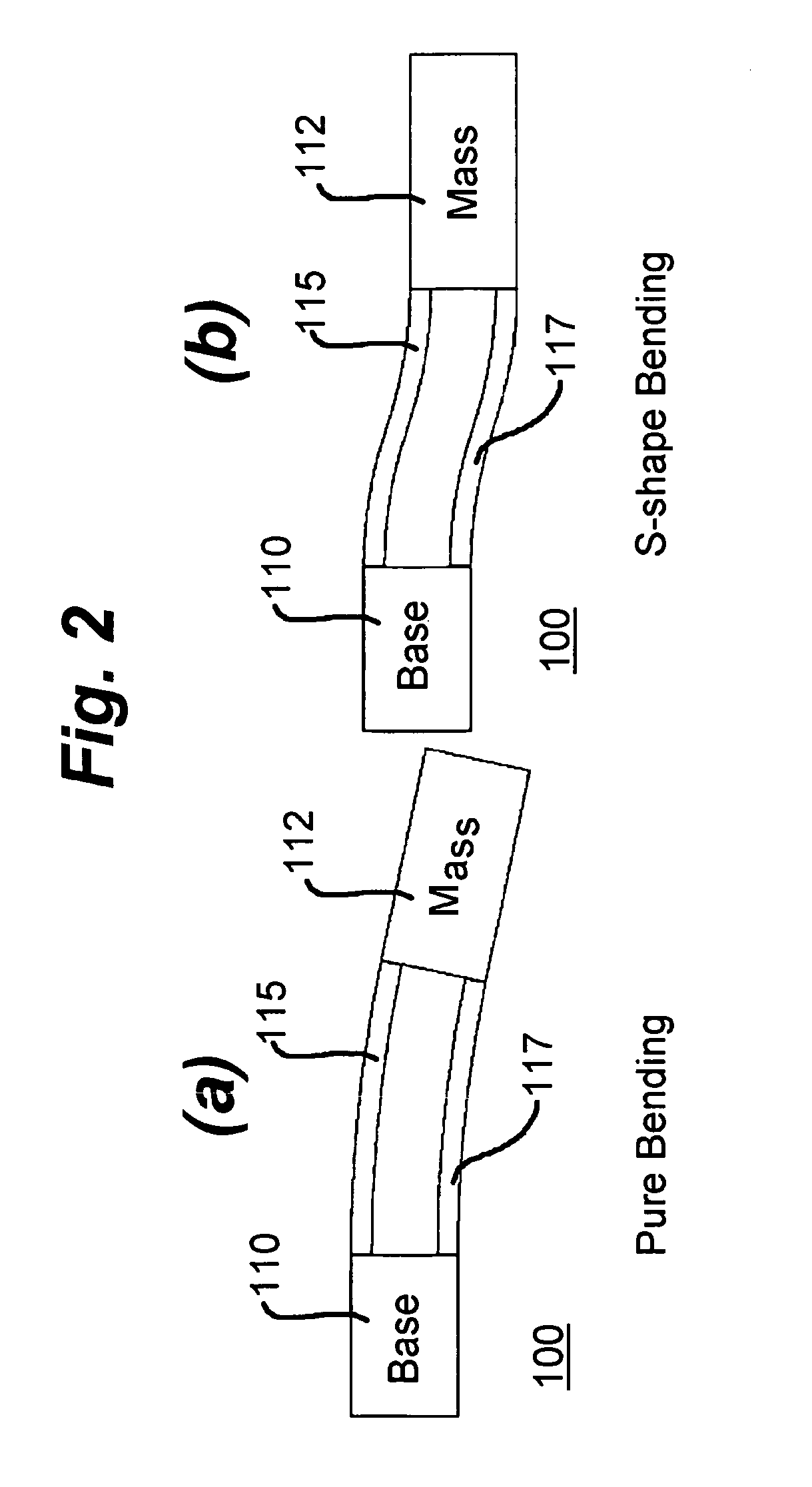
[0049]FIG. 1 is a simplified schematic representation of a vibration energy harvesting device 100 based on air-spaced piezoelectric cantilevers constructed in accordance with the present invention. In this embodiment of the invention, the voltage generated is proportional to the height of the air gap. An upper layer (beam) 115 and a bottom layer (beam) 117 are made, in this specific illustrative embodiment of the invention, of piezoelectric materials such as PZT (Lead Zirconate Titanate). Referring to upper layer 115, the thickness is t2, width is w2, and the length between a base 110 and a proof mass 112 is 1. With respect to bottom layer 117, the thickness is t1, width is w1, and the length between a base 110 and a proof mass 112 is 1. In some embodiments, however, particularly in an asymmetric arrangement, bottom layer 117 can be longer than upper layer 115. In this arrangement, bottom layer 117 is referr...


PUM


Abstract

An arrangement that converts mechanical energy into electrical energy employs a base member and a cantilever member coupled thereto. The cantilever member has two piezoelectric layers with an air space therebetween. A proof mass is coupled to the cantilever member distal from the base member. The first and second piezoelectric layers are formed of lead zirconate titanate (PZT), and the output voltage of the cantilever member is proportional to the height of the air gap. A piezoresistive accelerometer that is useful for measuring mechanical vibration has a suspension beam and a piezoresistive layer be separated from the suspension beam. A method of monitoring an acoustic vibration utilizes a piezoresistive element having an air-spaced cantilever formed of a piezoelectric material in the vicinity of the system to be monitored and obtains an alternating voltage form the air-spaced cantilever of the piezoresistive element.

Description

RELATIONSHIP TO OTHER APPLICATIONS[0001]This application claims the benefit of the filing date of U.S. Provisional Patent Application Ser. Nos. 60 / 932,862 (filed May 31, 2007); 60 / 932,847 (filed May 31, 2007); and 61 / 124,907 (filed Apr. 18, 2008). The disclosures in the identified United States Provisional patent applications are incorporated herein by reference.GOVERNMENT RIGHTS[0002]This invention was made with Government support by NSF Grant ECS-0501314. The Government may have certain rights in the invention.BACKGROUND OF THE INVENTION[0003]1. Field of the Invention[0004]This invention relates generally to piezoelectric devices, and more particularly, to a piezoelectric device based on air-spaced composite cantilever beams for vibration energy harvesting.[0005]2. Description of the Prior Art[0006]Piezo devices that are known in the art are based on conventional solid cantilevers. Since of the distance between the active layer and neutral plane is small in such known devices, the...

Claims


Application Information

Patent Timeline
IPC IPC(8): H01L41/04G01P15/09H02N2/18G01P15/12
CPCG01P15/09G01P15/0922H02N2/188H01L41/1136G01P15/123H10N30/306
Inventor XU, YONGWANG, ZHUOZHENG, QINGLONG
Owner WAYNE STATE UNIV
Why Eureka
Try Eureka