Position detector

Inactive Publication Date: 2010-10-28
PANASONIC CORP
View PDF37 Cites 17 Cited by
  • Summary
  • Abstract
  • Description
  • Claims
  • Application Information

AI Technical Summary

Benefits of technology

[0025]The configuration makes it possible to intensify changes in electrostatic capacitance simultaneously pursue a reduction in adjacent-interline capacitance.
[0026]According to the present invention, in connection with position detection utilizing a change in electrostatic capacitance, amounts of relative changes in electrostatic capacitance can be increased. Therefore, when detection

Problems solved by technology

Thus, the large-size panel encounters a problem of being susceptible to influenc

Method used


Image

  • Position detector
  • Position detector
  • Position detector

Examples


first embodiment

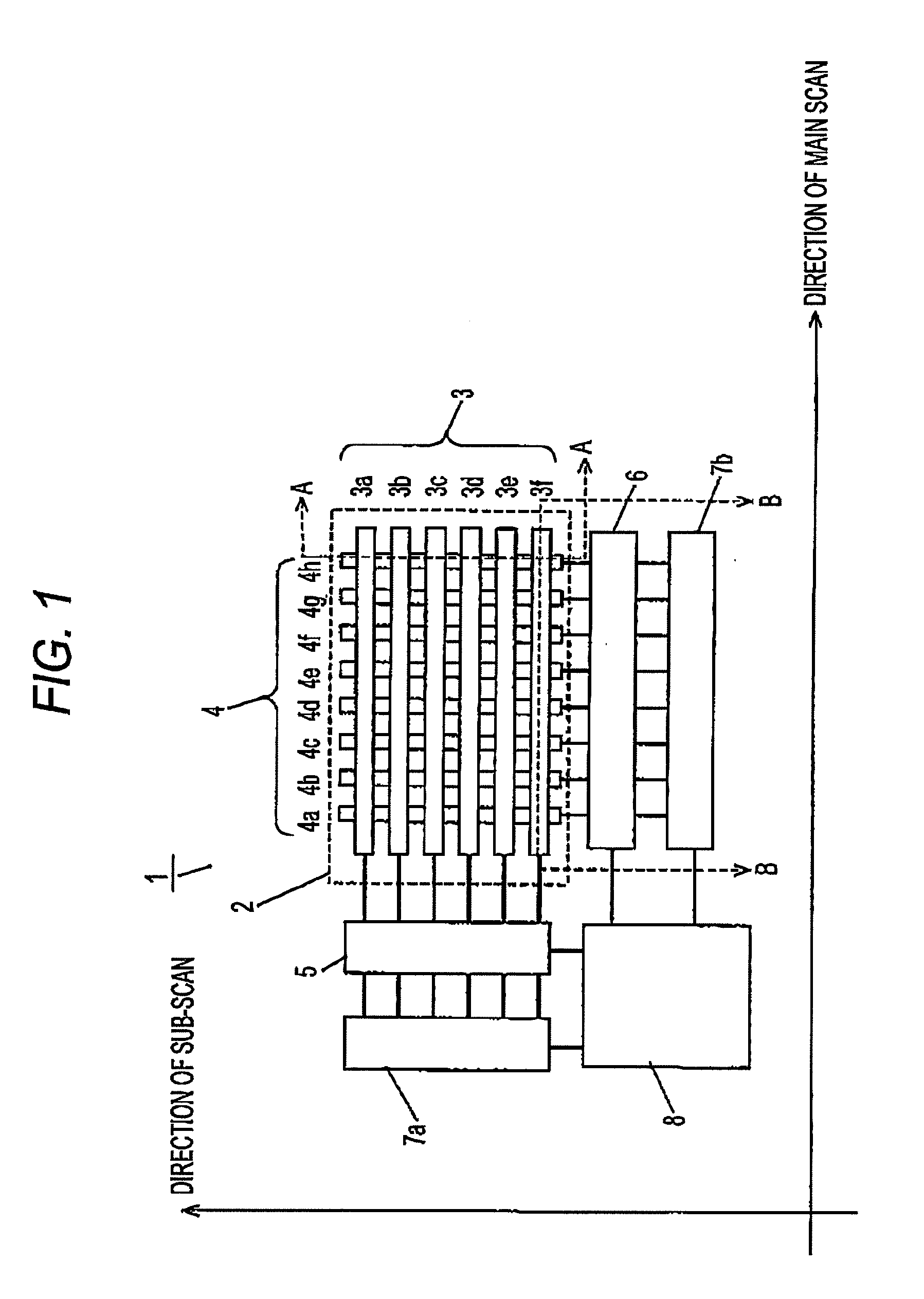
[0043]FIG. 1 is a schematic diagram of a position detector of a first embodiment of the present invention.

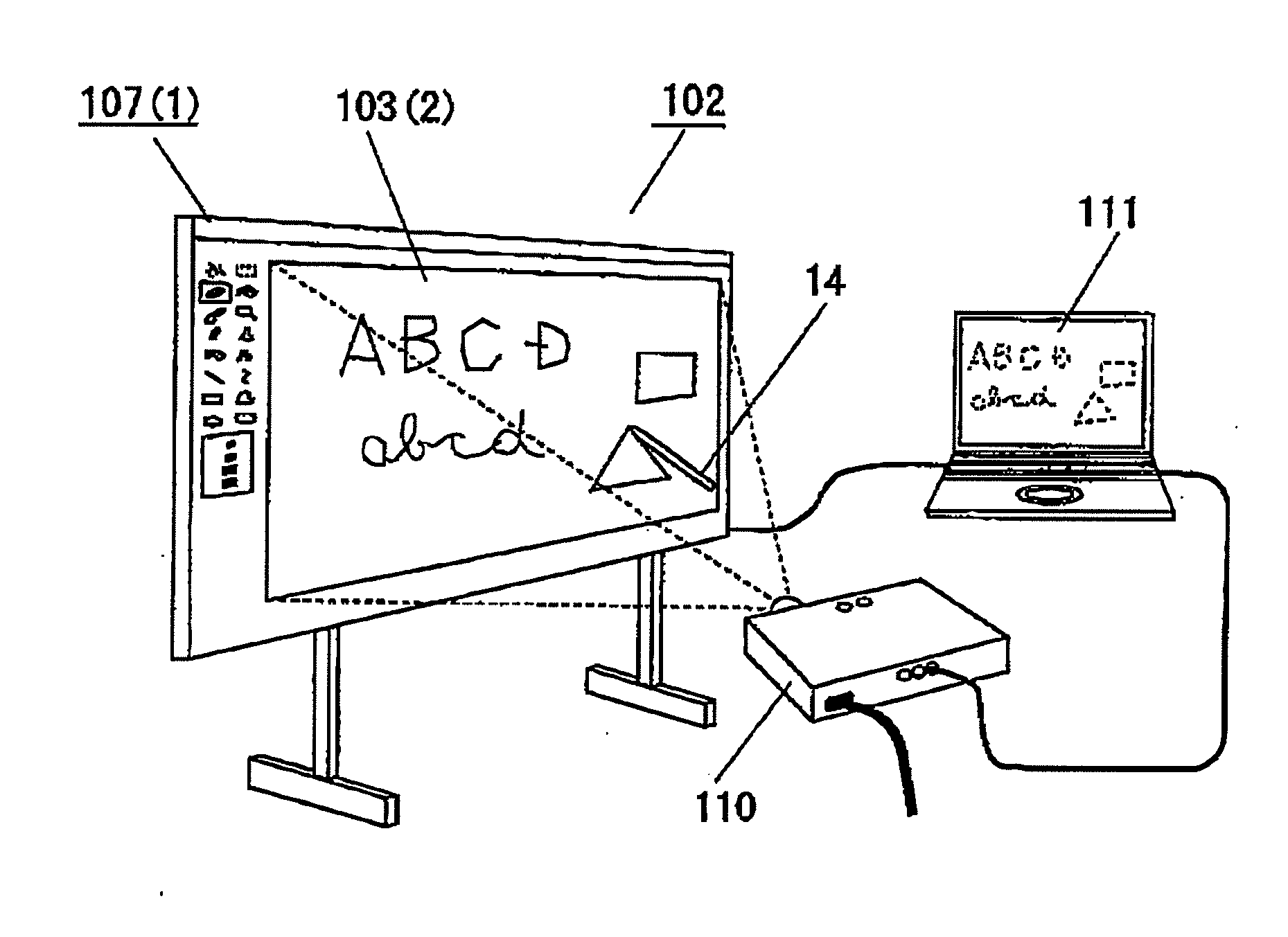
[0044]In FIG. 1, reference numeral 1 designates a position detector that is positioned on a videos screen of; for instance, a display, or built in an electronic white board (a surface of the actual position detector 1 is covered with a protective layer to be described later, and a configuration shown in FIG. 1 is not directly viewable). Reference numeral 2 designates a detection panel that accounts for the majority of the entirety of the position detector 1. A user brings a position pointing member 14 (not shown), such as a finger and a stylus pen, into contact with a surface of the detection panel 2. The user can thereby directly point a content projected or displayed on the surface of the detection panel 2 or coordinates of a position on an electronic white board, a tablet, and the like, to thus be able to input the coordinates to an information processing apparatus, such as a...

second embodiment

[0125]FIG. 9 is an oblique perspective view of a principal part showing the configuration of a position detector of a second embodiment of the present invention.

[0126]In the second embodiment, the gas layer (space) 15 is interposed between the support member 11 and the protective layer (the front member) 12. Since the layout of the detection electrodes, the structure of the support member 11, electrical operation, and the like, of the present embodiment are the same as their respective counterparts described in connection with the first embodiment, their explanations are omitted.

[0127]As shown in FIG. 9, the position detector 1 of the second embodiment has indentations that are provided, in the detection panel 2, on a support-member-side surface of the protective layer (the front member) 12 which the position pointing member 14 (not shown) contacts. The gas layer (space) 15 is consequently provided between the protective layer and the support member 11.

[0128]The protuberances 31 are...

third embodiment

[0134]FIG. 10 is an oblique perspective view of a principal part showing the configuration of a position detector of a third embodiment of the present invention.

[0135]In the third embodiment, the gas layer (space) 15 is provided in the support element 11. Since the layout of the detection electrodes, the structure of the protective layer (the front member) 12, electrical operation, and the like, of the present embodiment are the same as their respective counterparts described in connection with the first embodiment, their explanations are omitted.

[0136]As shown in FIG. 10, the position detector 1 of the third embodiment has the gas layer (space) 15 provided in the support member 11 having the first electrodes 3 and the second electrodes 4 arranged thereon in the detection panel 2.

[0137]Specifically, in the third embodiment, the support member 11 is configured in such a way that a remaining area except an area of the support member where the first electrodes 3 and the second electrod...


PUM


Abstract

There is provided a multilayer made up of: a support member 11 with first electrodes 3 including a plurality of electrodes arranged parallel to each other and the second electrodes 4 including a plurality of electrodes that are arranged parallel to each other so as to cross the first electrodes 3; a protective layer (a front member) 12 that is provided opposite one side of the support member 11 and with which a predetermined position pointing member is brought into contact; and a reinforcing material (a rear member) 13 provided opposite the other side of the support member 11. A gas layer (space) 15 is provided between the first electrodes 3 or the second electrodes 4 and at least one of the support member 11, the protective layer (the front member) 12, and the reinforcing material (the rear member) 13, thereby blocking electrical coupling paths that increase electrostatic capacitance C.

Description

BACKGROUND[0001]1. Field of the Invention[0002]The present invention relates to a position detector used in various information terminals, and the like, requiring a touch input performed with a finger and a stylus pen.[0003]2. Description of the Related Art[0004]In order to enhance a man-machine interface, information terminals that enable performance of a touch input, such as a touch panel and a tablet, have already been on the market. Position detectors are used as means for embodying a touch input. A position detector generally detects a position on a surface of a panel, or the like, touched with a finger or a stylus pen (hereinafter often called a “position pointing member”). The thus-detected contact position is converted into predetermined positional information, and the information terminal is configured so as to carry out various processing in accordance with the positional information.[0005]A configuration for detecting a position contacted with a position pointing member d...

Claims


Application Information

Patent Timeline
IPC IPC(8): G01R27/26
CPCG06F3/044G06F3/0443G06F3/0446G06F3/0445
Inventor KOUNO, HARUHIKO
Owner PANASONIC CORP
Why Eureka
Try Eureka