Comparison circuit, integrated circuit device and electronic apparatus

a technology of integrated circuits and electronic devices, applied in the direction of pulse manipulation, pulse technique, instruments, etc., can solve the problem of difficulty in setting the hysteresis width to the optimum valu

Inactive Publication Date: 2010-10-28
SEIKO EPSON CORP
View PDF1 Cites 7 Cited by
  • Summary
  • Abstract
  • Description
  • Claims
  • Application Information

AI Technical Summary

Problems solved by technology

However, with these techniques, there has been a problem in that it is difficult to set the hysteresis wid

Method used


Image

  • Comparison circuit, integrated circuit device and electronic apparatus
  • Comparison circuit, integrated circuit device and electronic apparatus
  • Comparison circuit, integrated circuit device and electronic apparatus

Examples


Embodiment Construction

[0044]Hereafter, a detailed description will be given of a preferred embodiment of the invention. The embodiment, to be described hereafter, does not unduly limit the contents of the invention which are described in the claims, and not all of the configurations described in the embodiment are essential as solution means of the invention.

[0045]1. First Basic Configuration Example

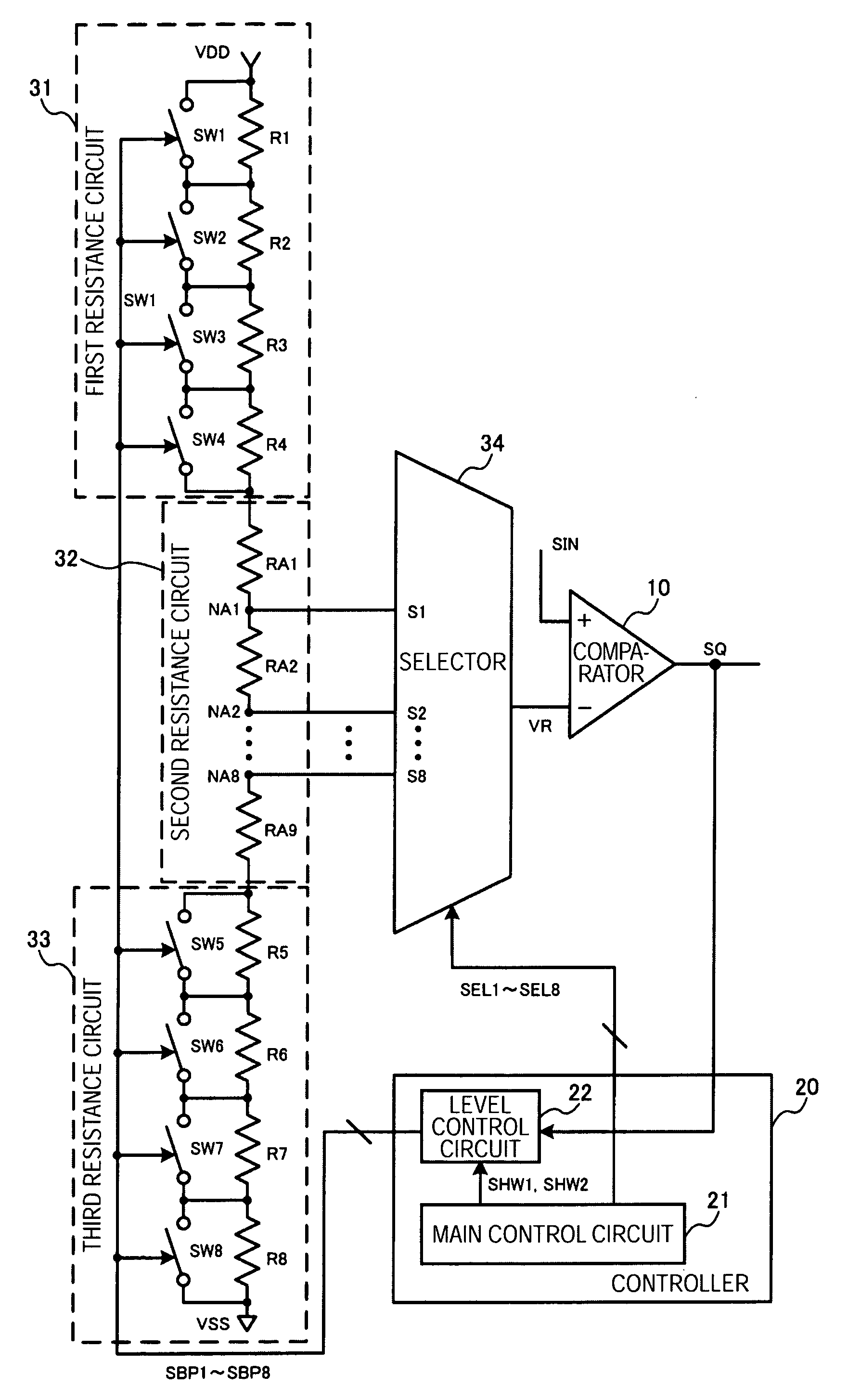
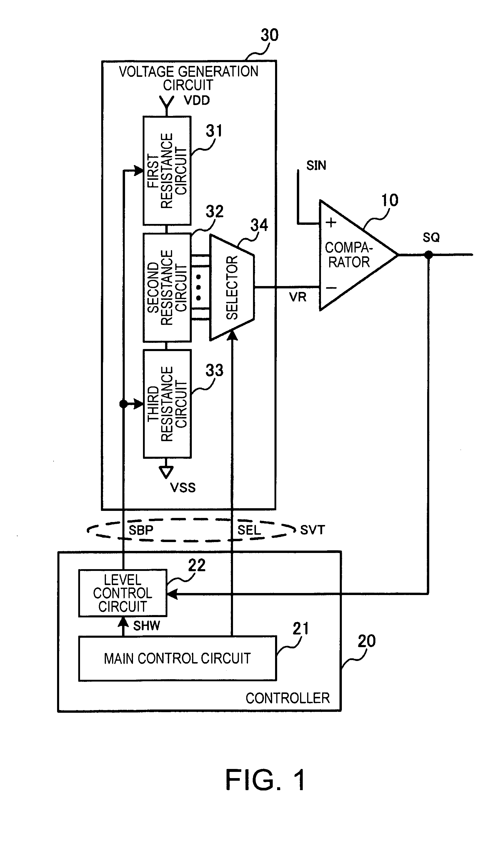
[0046]FIG. 1 shows a first basic configuration example of a comparison circuit of the embodiment. The comparison circuit of the embodiment includes a comparator 10, a controller 20, and a voltage generation circuit 30. An input signal SIN is input into a first input terminal (a non-inverting input terminal, a+input terminal) of the comparator 10, a reference voltage VR for comparison is input into a second input terminal (an inverting input terminal, a−input terminal) thereof, and the comparator outputs an output signal SQ. The controller 20 monitors the output signal SQ of the comparator 10. A threshold volt...


PUM


Abstract

A comparison circuit includes a comparator into a first input terminal of which an input signal is input, and into a second input terminal of which a reference voltage for comparison is input, a controller which monitors an output signal of the comparator, and a voltage generation circuit into which a threshold voltage control signal from the controller is input, wherein the voltage generation circuit, when the voltage level of the output signal of the comparator is a first level, outputs as the reference voltage a first threshold voltage which is one of a high potential side threshold voltage and a low potential side threshold voltage which define a hysteresis width, and when the voltage level of the output signal of the comparator is a second level, outputs as the reference voltage a second threshold voltage which is the other one of the high potential side threshold voltage and low potential side threshold voltage.

Description

[0001]The present application, claiming priority based on Japanese Patent Application No. 2009-108981 filed as of Apr. 28, 2009, is incorporated in the specification.TECHNICAL FIELD[0002]An aspect of the present invention relates to a comparison circuit, an integrated circuit device, an electronic apparatus.BACKGROUND ART[0003]In recent years, a sensor network has attracted attention wherein, with a plurality of sensors connected via a network, a situation is comprehensively determined by acquiring information from each of the sensors. With this kind of sensor network, various sensors are used, such as a temperature sensor, a smoke sensor, an optical sensor, a human presence sensor, a pressure sensor, a living organism sensor, and a gyro sensor.[0004]However, as detection signals (sensor signals) of the sensors are analog signals, in order to carry out processes of analyzing and determining the information by means of a CPU or the like, it is necessary to amplify the analog signals,...

Claims


Application Information

Patent Timeline
IPC IPC(8): H03L5/00
CPCH03K5/24
Inventor MURASHIMA, NORIYUKI
Owner SEIKO EPSON CORP
Why Eureka
Try Eureka