Cnt-based signature control material

a technology of signature control and absorbing materials, applied in the direction of shielding materials, localised screening, transportation and packaging, etc., can solve the problems of inherently non-structural nature, prone to wear, chipping, failure, etc., and achieve the effect of dispersing the energy of absorbed radar and reducing radar reflectan

Active Publication Date: 2010-10-28
APPL NANOSTRUCTURED SOLUTIONS LLC
View PDF104 Cites 56 Cited by
  • Summary
  • Abstract
  • Description
  • Claims
  • Application Information

AI Technical Summary

Benefits of technology

[0007]In some aspects, embodiments disclosed herein relate to a radar absorbing composite that includes a (CNT)-infused fiber material disposed in at least a portion of a matrix material. The composite is capable of absorbing rada

Problems solved by technology

However, the RAMs presently employed have some drawbacks.
Instead, the RAMs are applied as coatings or paints over the surface of the low observable structure making them heavier, and prone to wear, chipping, and failure.
Moreover, these coatings require bonding to the surface of the structure because they are not an integrated part of the structure or surface.
Such RAMs are inherently non-structural in nature s

Method used


Image

  • Cnt-based signature control material
  • Cnt-based signature control material
  • Cnt-based signature control material

Examples


example

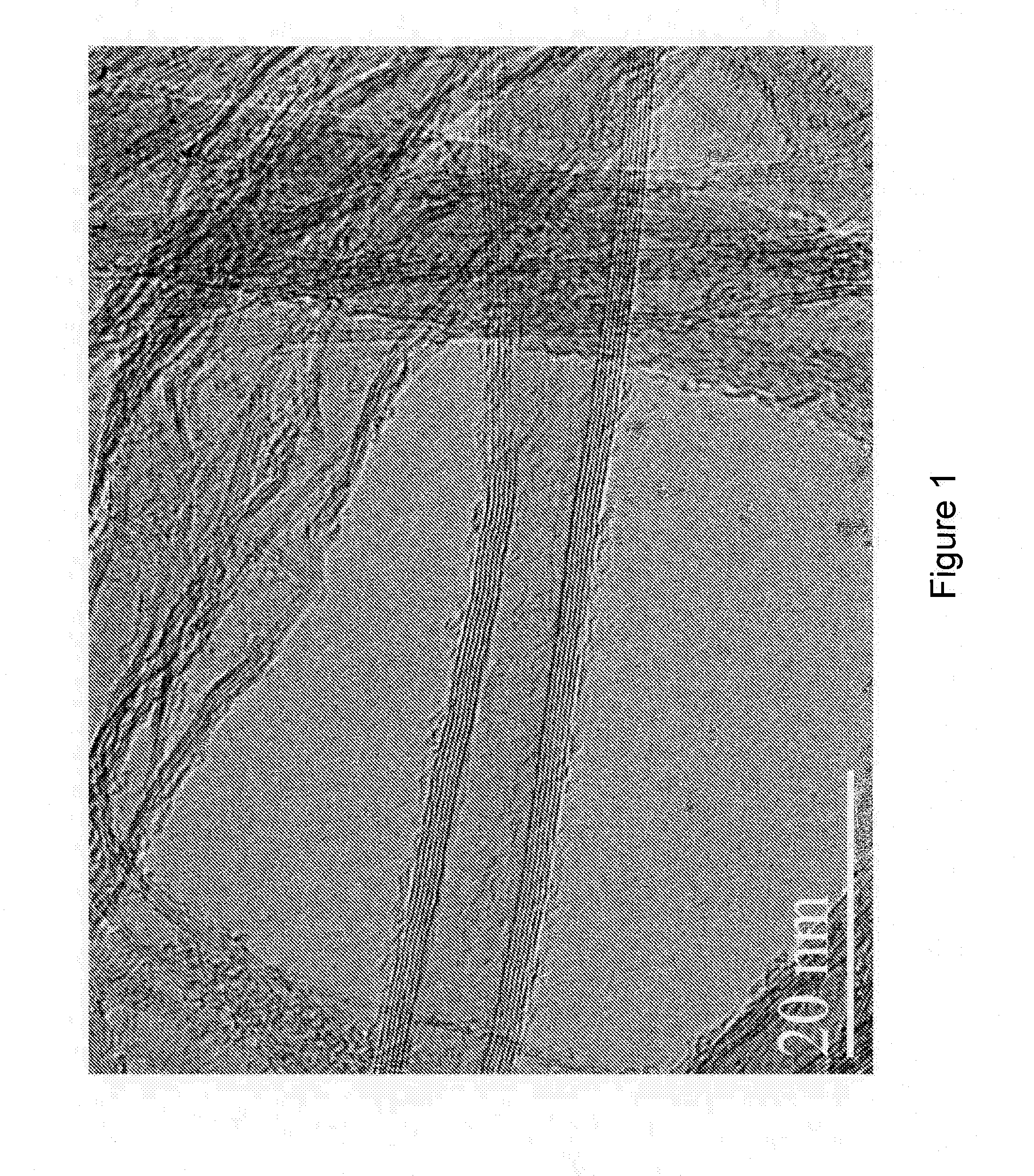
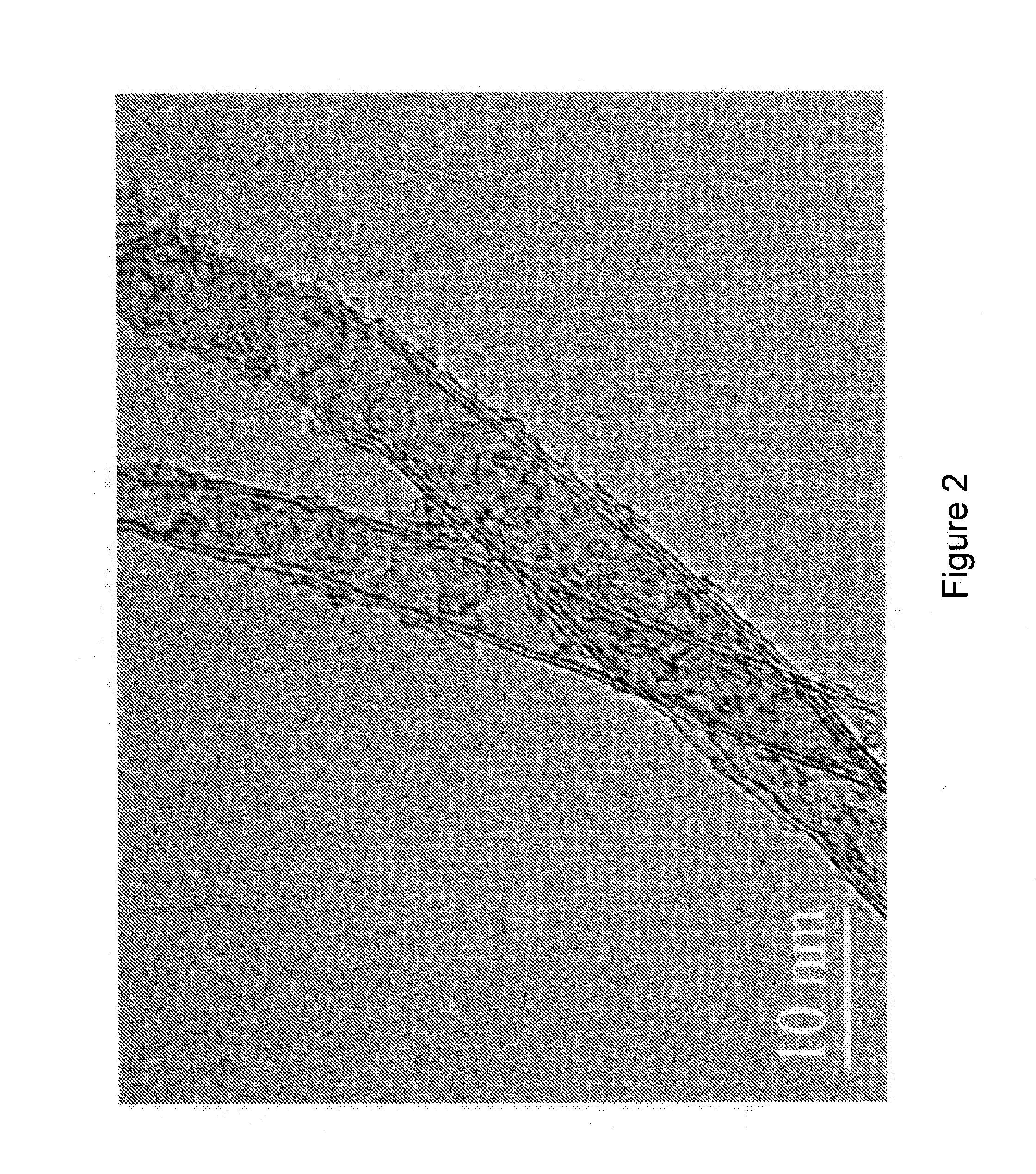
[0157]This example shows how a carbon fiber material can be infused with CNTs in a continuous process to enhance signature control capabilities in composite structures.

[0158]In this example, the maximum loading of CNTs on fibers is targeted. 34-700 12 k carbon fiber tow with a tex value of 800 (Grafil Inc., Sacramento, Calif.) is implemented as the carbon fiber substrate. The individual filaments in this carbon fiber tow have a diameter of approximately 7 μm.

[0159]FIG. 12 depicts system 800 for producing CNT-infused fiber in accordance with the illustrative embodiment of the present invention. System 800 includes a carbon fiber material payout and tensioner station 805, sizing removal and fiber spreader station 810, plasma treatment station 815, barrier coating application station 820, air dry station 825, catalyst application station 830, solvent flash-off station 835, CNT-infusion station 840, fiber bundler station 845, and carbon fiber material uptake bobbin 850, interrelated as ...


PUM

PropertyMeasurementUnit
Percent by massaaaaaaaaaa
Densityaaaaaaaaaa

Abstract

A radar absorbing composite includes a (CNT)-infused fiber material disposed in at least a portion of a matrix material. The composite absorbs radar in a frequency range from about 0.10 Megahertz to about 60 Gigahertz. The CNT-infused fiber material forms a first layer that reduces radar reflectance and a second layer that dissipates the energy of the radar. A method of manufacturing this composite includes disposing a CNT-infused fiber material in a portion of a matrix material with a controlled orientation of the CNT-infused fiber material within the matrix material, and curing the matrix material. The composite can be formed into a panel which is adaptable as a structural component of a transport vessel or missile for use in stealth applications.

Description

STATEMENT OF RELATED APPLICATIONS[0001]This application claims the benefit of U.S. Provisional Application No. 61 / 173,435, filed Apr. 28, 2009, and U.S. Provisional Application No. 61 / 172,503, filed Apr. 24, 2009, both of which are incorporated herein by reference in their entirety.FIELD OF INVENTION[0002]The present invention relates to generally to radar absorbing materials.BACKGROUND[0003]Low observable, or stealth, technology is utilized on aircrafts, ships, submarines, and missiles, for example, to make them less visible or observable to radar, infrared, sonar and other detection methods. Various radar absorbing materials (RAMs), which absorb electromagnetic frequencies, such as in the radar range, have been developed for such low observable applications. However, the RAMs presently employed have some drawbacks. For example, many RAMs are not an integral part of the surface of a low observable structure. Instead, the RAMs are applied as coatings or paints over the surface of th...

Claims


Application Information

Patent Timeline
IPC IPC(8): H01Q17/00B32B9/00B32B5/26B32B33/00
CPCH01B1/18H05K9/009H01Q17/002H01B1/24Y10T428/249924G02B6/12H01B1/02H01B1/04H05K9/003H05K9/0069H05K9/0073H05K9/0081
Inventor SHAH, TUSHAR K.MALECKI, HARRY C.
Owner APPL NANOSTRUCTURED SOLUTIONS LLC
Why Eureka
Try Eureka