Imaging optical system and range finder

an optical system and optical system technology, applied in the field of compact imaging optical systems, can solve the problems of insufficient brightness of the above-mentioned optical system, insufficient brightness of the optical system using the reflecting mirror, and insufficient development, so as to reduce the size of the display, prevent vignetting, and increase the angle of view

Active Publication Date: 2010-10-28
NALUX CO LTD
View PDF3 Cites 10 Cited by
  • Summary
  • Abstract
  • Description
  • Claims
  • Application Information

AI Technical Summary

Benefits of technology

[0011]When the relational expressions described above are satisfied, an imaging optical system which is compact and is sufficiently bright for use with infrared light can be obtained.
[0012]According to the aspect of the invention, the layout size can be reduced and vignetting can be prevented. Further, the angle of view can be increased and telecentricity of the angle of view of light reaching the image plane (degree of how orthogonally the reaching light travels to the image plane) can be improved. Further, a space for setting a light shielding plate can be obtained between the first reflection surface and the second reflection surface. Further, stray light reaching the image plane can be shielded as much as possible.
[0013]Since the imaging optical system is configured such that the optical axis at the center of the field of view and the optical axis of the image plane are in parallel to each other, focusing can be easily performed by a simple mechanism such as screws.
[0014]Since at least one of the three reflection surfaces is rotationally asymmetric, curvature of field and comatic aberration can be easily removed.

Problems solved by technology

However, the imaging optical system described above is not bright enough to be used for infrared imaging devices such as infrared cameras.
An imaging optical system using reflecting mirrors which is compact enough to be mounted on vehicles or the like and is sufficiently bright has not been developed.
When F-number is greater than the value, the beam spot will be larger than the pixel size of the commercially available infrared imaging element and therefore the optical system cannot meet requirement of resolution of the infrared imaging element.
So, imaging optical systems used for visible lights can hardly be used for far-infrared lights.
On the contrary, in optical systems using refraction it is almost unnecessary to study effects of stray lights.

Method used


Image

  • Imaging optical system and range finder
  • Imaging optical system and range finder
  • Imaging optical system and range finder

Examples


example 1

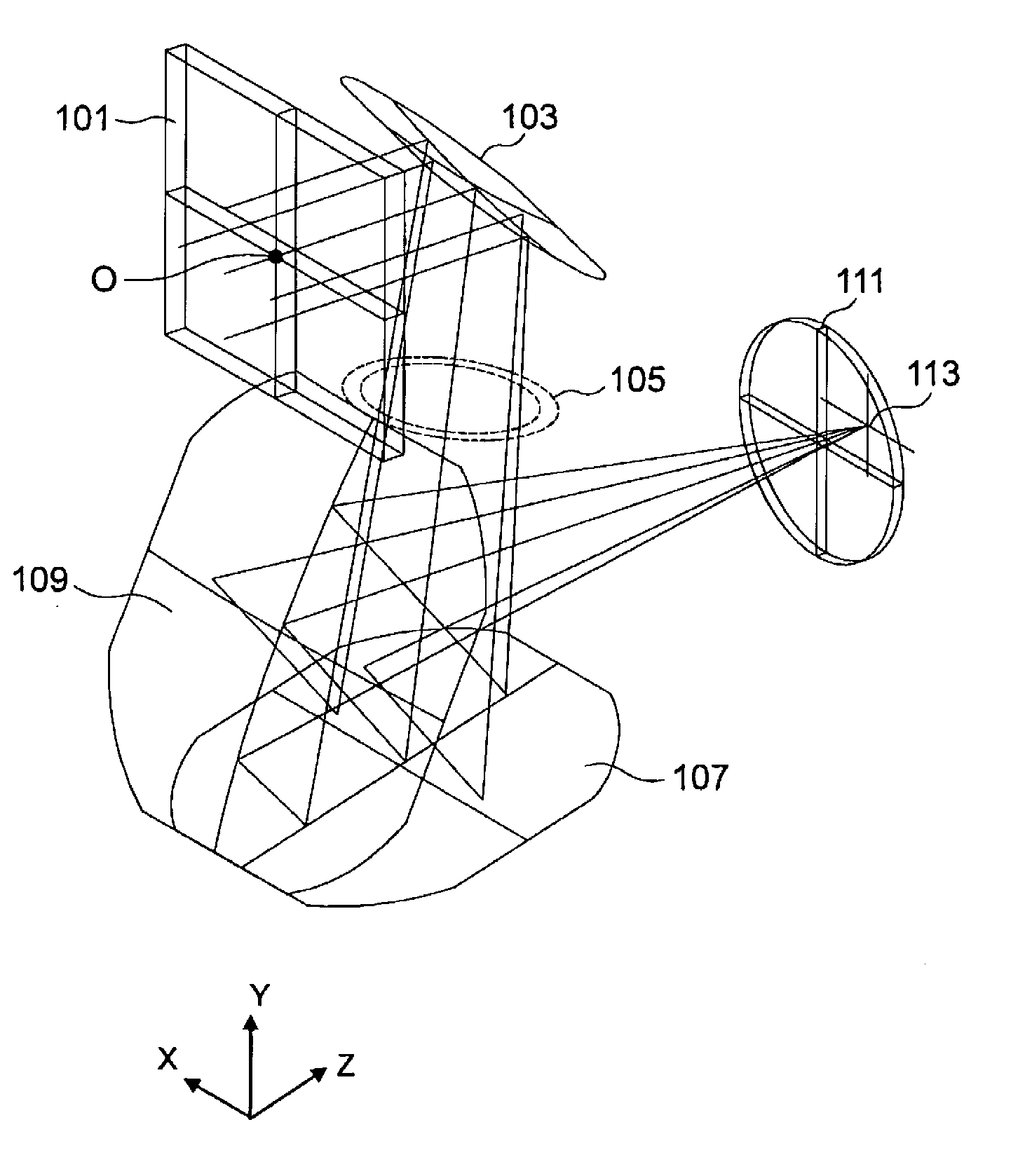
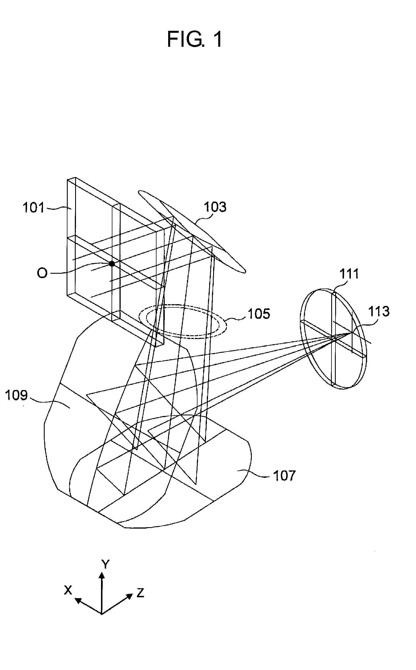
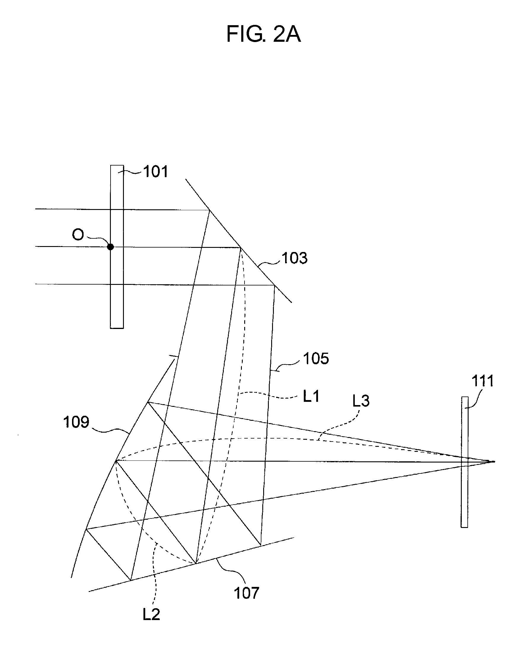
[0154]Table 6 shows specifications of an imaging optical system of Example 1.

TABLE 6OriginOriginOriginRotationPointPointPointangleSurfacepositionpositionpositionYZ sectionRefractiveSurfacenumberNoteX(mm)Y(mm)Z(mm)(deg)indexshapeObjectObject00infinity01flatsurfacesurfacesurfaceSurface 1Window00004.003flatplatesurfaceSurface 2Window00201flatplatesurfaceSurface 3First0020491XYreflectionpolynomialsurfacesurfaceStopAperture0−19.80522.783901flatsurfacestopsurfaceSurface 5Second0−46.54326.541721XYreflectionpolynomialsurfacesurfaceSurface 6Third0−33.59439.045231XYreflectionpolynomialsurfacesurfaceSurface 7Window0−33.59411.04504.003flatplatesurfaceSurface 8Window0−33.59410.04501flatplatesurfaceImageImage0−33.5945.94501flatplaneplanesurface

[0155]Table 7 shows coefficients that determine the shapes of the first to third reflection surfaces.

TABLE 7Surface 3Surface 5Surface 6X22.10E−035.15E−03−3.27E−03Y21.05E−034.58E−03−2.20E−03X2Y−6.10E−06−3.05E−05−6.85E−05Y3−1.44E−06−2.49E−05−5.53E−05X47.85E−0...

example 2

[0161]Table 8 shows specifications of an imaging optical system of Example 2.

TABLE 8OriginOriginOriginRotationPointPointPointangleSurfacepositionpositionpositionYZ sectionRefractiveSurfacenumberNoteX(mm)Y(mm)Z(mm)(deg)indexshapeObjectObject00infinity01flatsurfaceSurfacesurfaceSurface 1Window00004.003flatPlatesurfaceSurface 2Window00201flatPlatesurfaceSurface 3First0−3.18620.57039.6361XYreflectionpolynomialsurfacesurfaceStopAperture0−17.82517.49582.0001flatsurfaceStopsurfaceSurface 5Second0−45.76621.469104.3811XYReflectionpolynomialsurfacesurfaceSurface 6Third0−33.3120.431153.0811XYReflectionpolynomialsurfacesurfaceSurface 7Window0−32.76354.0670.0004.003flatplatesurfaceSurface 8Window0−32.76355.0670.0001flatplatesurfaceImageImage0−32.76359.1670.0001flatplaneplanesurface

[0162]Table 9 shows coefficients that determine the shapes of the first to third reflection surfaces.

TABLE 9Surface 3Surface 5Surface 6X24.45E−032.30E−03−5.22E−03Y22.11E−033.55E−03−5.17E−03X2Y−1.09E−05−2.49E−05−9.28E−0...

example 3

[0168]Table 10 shows specifications of an imaging optical system of Example 3.

TABLE 10OriginOriginOriginRotationPointPointPointangleSurfacepositionpositionpositionYZ sectionRefractiveSurfacenumberNoteX (mm)Y (mm)Z (mm)(deg)indexshapeObjectObject00infinity01flatsurfacesurfacesurfaceSurface 1Window00004.003flatplatesurfaceSurface 2Window00201flatplatesurfaceSurface 3First00.00020.00039.0001XYreflectionpolynomialsurfacesurfaceStopAperture0−17.60716.25878.0001FlatsurfacestopsurfaceSurface 5Second0−49.8869.397103.0001XYreflectionpolynomialsurfacesurfaceSurface 6Third0−33.337−3.532154.0001XYreflectionpolynomialsurfacesurfaceSurface 7Window0−33.33730.4680.0004.003flatplatesurfaceSurface 8Window0−33.33743.4680.0001flatplatesurfaceImageImage0−33.33744.4680.0001flatplaneplanesurface

[0169]Table 11 shows coefficients that determine the shapes of the first to third reflection surfaces.

TABLE 11Surface 3Surface 5Surface 6X23.25E−032.11E−03−5.14E−03Y22.43E−032.67E−03−3.36E−03X2Y5.12E−06−3.60E−061.9...


PUM


Abstract

An imaging optical system includes three reflecting mirrors having first to third reflection surfaces and is configured, such that in an XYZ orthogonal coordinate system using an optical axis at the center of the field of view as Z-axis, the optical axis at the center of the field of view and an optical axis of an image plane are in parallel to each other by changing orientation of the optical axis in a YZ section while maintaining the orientation of the optical axis in an XZ section. At least one of the three reflection surfaces is rotationally asymmetric. Assuming that along the path of the beam traveling along the optical axis at the center of the field of view a distance between the second reflection surface and the third reflection surface is L2, a distance between the third reflection surface and the image plane is L3 and fy1 and an equivalent F-number of the imaging optical system is represented as Fno, the relational expression
0.5<Fno(L2/L3)<1.3
is satisfied.

Description

CROSS-REFERENCE RELATED APPLICATIONS[0001]This is a Continuation-in-Part (CIP) application of International Application No. PCT / JP2008 / 070355, filed Nov. 7, 2008, and is also a Continuation-in-Part (CIP) application of International Application No. PCT / JP2007 / 071844, filed Nov. 9, 2007. The disclosure of the prior applications is hereby incorporated by reference herein in its entirety.FIELD OF THE INVENTION[0002]The present invention relates to an imaging optical system using reflecting mirrors. Particularly, the invention relates to a compact imaging optical system for infrared light using reflecting mirrors.BACKGROUND ART[0003]If an imaging optical system for infrared imaging devices is realized by transmission optical elements such as lenses, it is necessary to use germanium as a raw material and the price rises.[0004]Accordingly, to realize a low-price imaging optical system, an imaging optical system using reflecting mirrors is preferable. An imaging optical system using reflec...

Claims


Application Information

Patent Timeline
Patent Type & Authority Applications(United States)
IPC IPC(8): G02B17/06
CPCG02B17/0642G02B7/1825
Inventor SAKAGAMI, NORIHISAFUJIOKA, TAKAHIROHATADE, KOUEI
Owner NALUX CO LTD
Why Eureka
Try Eureka