High performance outboard section for rotor blades

a rotor blade and high-performance technology, applied in the field of rotor blades, can solve the problems of rotor noise level increase, rotor efficiency decrease, oscillatory rotor load and vibration of rotor blades, etc., and achieve the effects of improving efficiency, improving efficiency, and improving hover efficiency

Active Publication Date: 2010-10-28
KAREM ABE
View PDF10 Cites 25 Cited by
  • Summary
  • Abstract
  • Description
  • Claims
  • Application Information

AI Technical Summary

Benefits of technology

[0012]Contemplated methods include the steps of: (a) receiving information that efficiency can be improved with use of the inventive blades as discussed above; and then (b) provisioning (i.e., designing, manufacturing, fitting, and/or retrofitting) rotorcraft with one or more of such blades. Such information can be received internally, from a company's own designers and other agents, or externally from competitors or others. As used herein, the concept of improved efficiency relates to improvement by at least 5%-10%, with respect to same length blades having a swept back tip in only the outboard 10% of the blade, in at least one of (a) lift in highly loaded rotors, especially at higher altitudes and at forward speed; (b) higher hover efficiency (higher hover figure of merit); (c) increased maximum take-off weight; and (d) reduced rotor loads and rotorcraft noise and vibration, especially at high forward speed.
[0013]From another perspecti

Problems solved by technology

As any section of a rotor travels above Mach 0.7 and approaches Mach 1, transonic flow phenomena limit the maximum section lift, create shock waves, substantially increase rotor noise level, decrease rotor efficiency and/or cause oscillatory rotor loads and rotorcraft vibrations.
Additionally, to further delay the onset of these results rotorcraft with hi

Method used


Image

  • High performance outboard section for rotor blades
  • High performance outboard section for rotor blades
  • High performance outboard section for rotor blades

Examples


Embodiment Construction

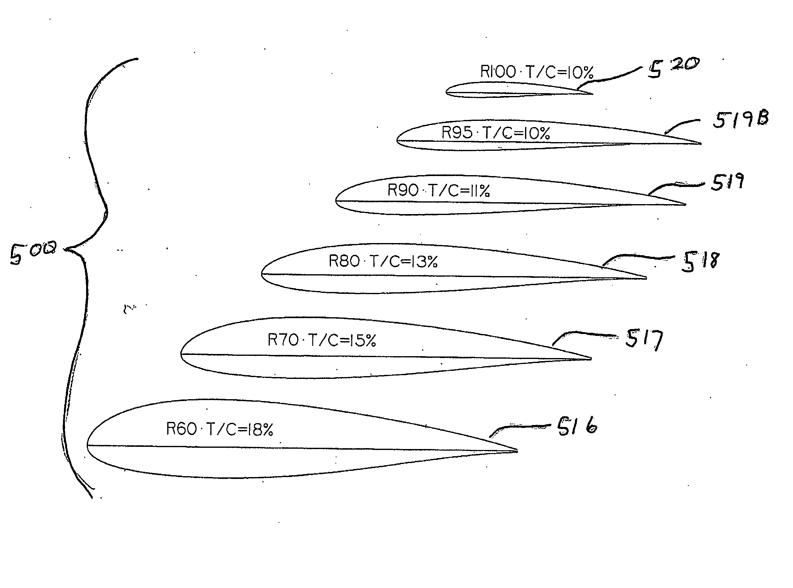
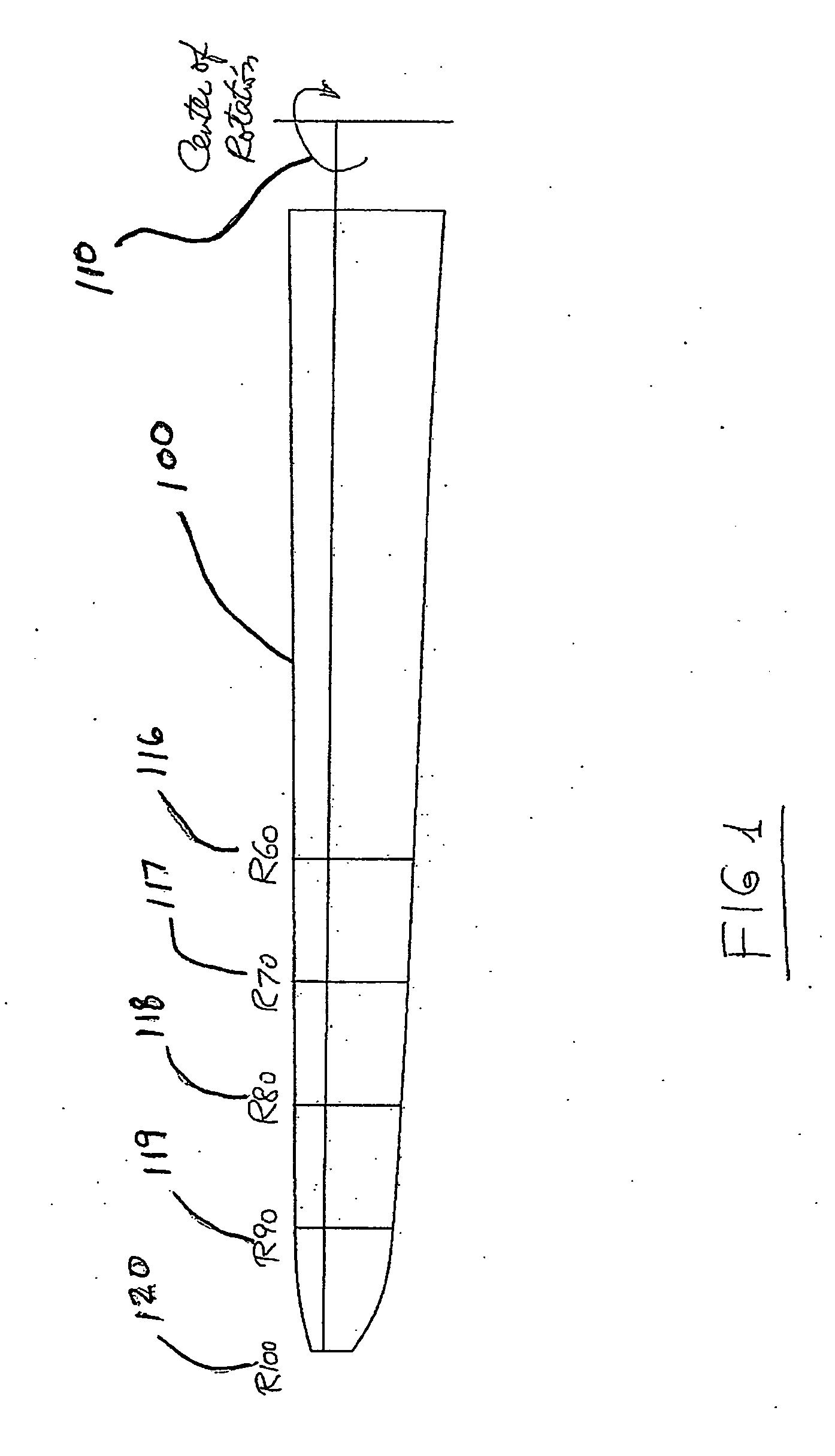
[0023]In FIG. 1, a rotor blade 100 has a center of rotation 110, and the Figure is marked 116-120 to designate percentage distances from the center of rotation of the blade to the tip. In accordance with one class of novel methods disclosed herein, whereby the blade was designed without taking into account the detrimental effects of the high Mach numbers on the blade from R63 to R100. The result is a blade that would hover at sea level at maximum RPM with a tip Mach number of only 0.72, the tip Mach number of the advancing blade at maximum forward speed in helicopter mode would be 0.9, and at R70 for the same conditions would be 0.68. These Mach numbers are excessive for efficient rotor operation and low noise level at the desired lift coefficients, and with the desired airfoil thicknesses of 15% at R70 and 10% at R100.

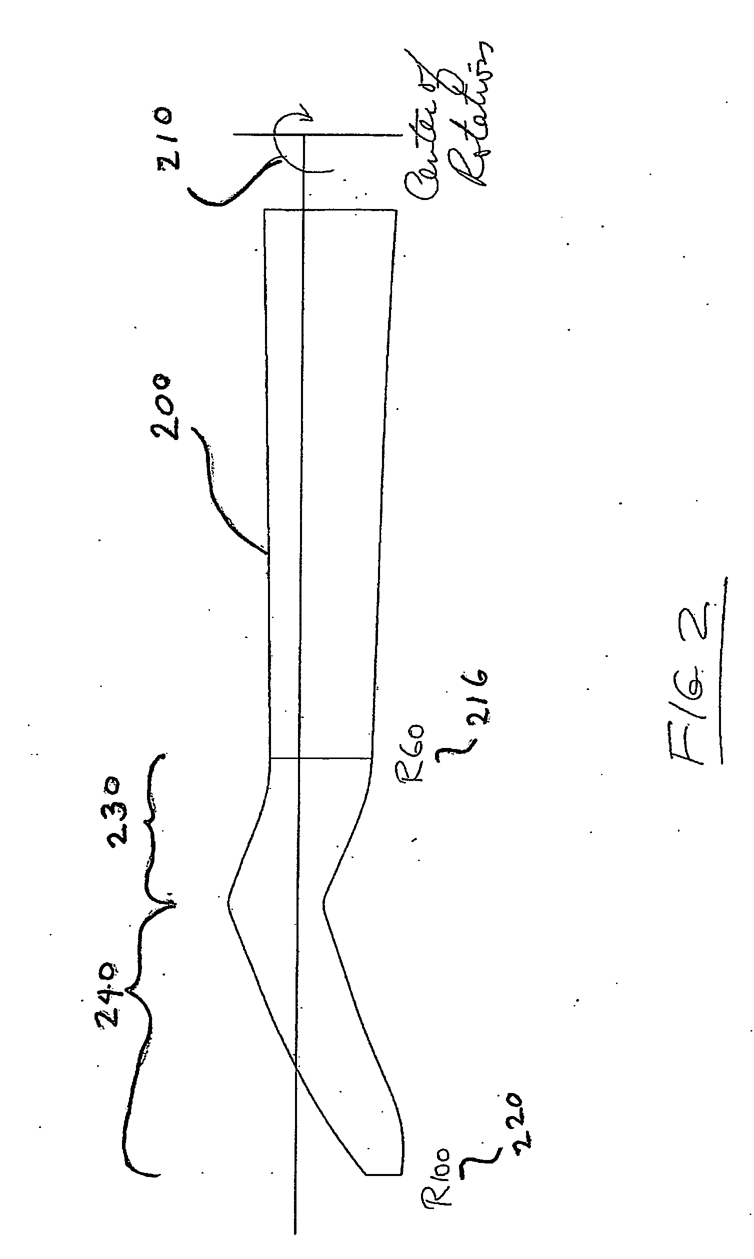
[0024]In FIG. 2, the blade design of FIG. 1 is modified to include forward swept 230 and aft swept 240 portions, which together provide a swept portion of at least 40...


PUM


Abstract

Blades for rotorcraft are designed and/or implemented with rotor blades having a swept portion that occupies at least 20-40% of a length of the blade. Forward and aft sweeps are contemplated, with up to 20° or more of sweep. The swept portion preferably has a thickness ration of at least 10-20% at R80, and can have a tapered planform with a relatively outboard section having a smaller chord than a relatively inboard section. Contemplated design methods include optimizing or otherwise designing the rotor blade planform and lift distribution along the blade for efficiency in various flight conditions without taking into account the detrimental effects of high Mach numbers, and then using sweep angle, airfoil thickness and transonic airfoil shaping to maintain the lift distribution, low drag and low noise level at real Mach numbers at the various blade stations at the various flight conditions.

Description

[0001]This application claims priority to U.S. Provisional Application Ser. No. 60 / 708,597 filed Aug. 15, 2005.FIELD OF THE INVENTION[0002]The field of the invention is rotorcraft.BACKGROUND OF THE INVENTION[0003]Most medium size and large rotorcraft have high ratio of maximum weight to rotor disc area, such ratio is called disc loading in the aeronautical vernacular.[0004]In order to generate the high required lift from the limited disc area, rotors of such rotorcraft turn at angular velocity (RPM) which causes the blade tips at hover at sea level to be close to 70% the speed of sound (Mach 0.7 in the aeronautical vernacular). Flying at higher altitude and / or at forward speed brings the tip speed closer to Mach 1.[0005]As any section of a rotor travels above Mach 0.7 and approaches Mach 1, transonic flow phenomena limit the maximum section lift, create shock waves, substantially increase rotor noise level, decrease rotor efficiency and / or cause oscillatory rotor loads and rotorcraf...

Claims


Application Information

Patent Timeline
IPC IPC(8): B64C11/26G06F17/50
CPCB64C27/467
Inventor KAREM, ABE
Owner KAREM ABE
Why Eureka
Try Eureka