Method for Coupling Stiffening Profile Elements and Structural Component

a technology of profile elements and structural components, applied in the direction of manufacturing tools, efficient propulsion technologies, transportation and packaging, etc., can solve the problems of chip falling into the cavity, noise and damage, and achieve the effect of reliable quality control

Active Publication Date: 2010-10-28
AIRBUS OPERATIONS GMBH
View PDF20 Cites 43 Cited by
  • Summary
  • Abstract
  • Description
  • Claims
  • Application Information

AI Technical Summary

Benefits of technology

[0010]It is therefore an object of this invention to provide an improved coupling for stiffening profile elements which, when assembled, includ

Problems solved by technology

Since this cavity is not easily accessible from outside the stringer, the problem arises, when coupling such stringers, that riveted joints between one flank of the ω-profile and a transverse butt strap arranged flush to it, on the side of the stringer, projects into the inaccessible cavity, from where it cannot be examined for quality control.
One further problem lies in the fact that when d

Method used


Image

  • Method for Coupling Stiffening Profile Elements and Structural Component
  • Method for Coupling Stiffening Profile Elements and Structural Component
  • Method for Coupling Stiffening Profile Elements and Structural Component

Examples


Embodiment Construction

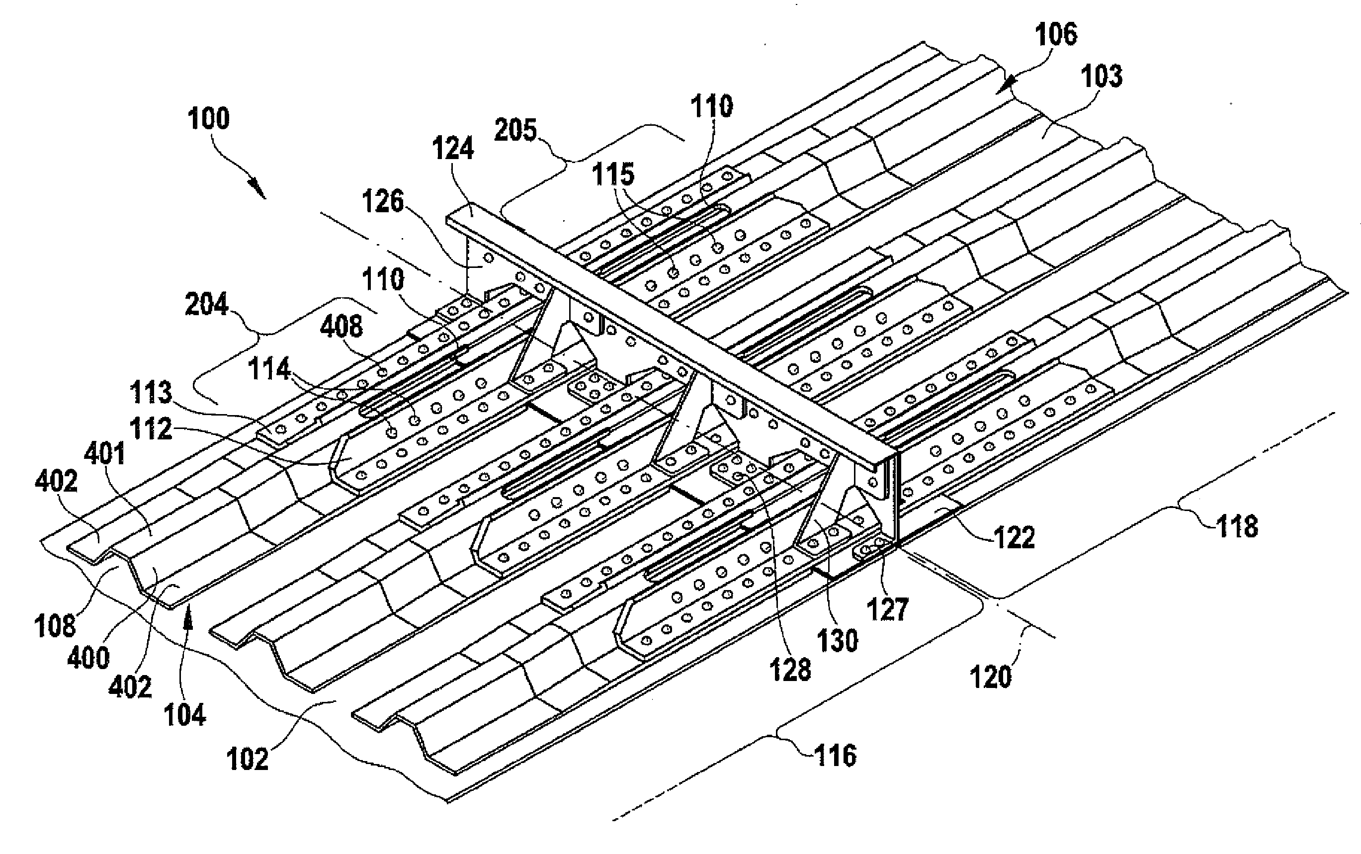
[0036]FIG. 1 shows in a perspective view, and sectionally, a structural component 100, which forms part of the fuselage shell of an aircraft, one's vision being directed to the inside of outer skin 102, 103 of the aircraft. The fuselage shell is joined together from a plurality of sections 116, 118 along seam lines 120 running annularly around the aircraft fuselage. The section shown in FIG. 1 comprises a part of a first 116 and a second 118 section whose seam point is denoted by the dash-dot line 120.

[0037]The first section 116 comprises a first further section 102, and second section 118 comprises a second further section 103 of outer skin 102, 103. Both outer skin sections abut each other along seam line 120, so that no step is formed on the smooth outside of the aircraft fuselage facing away from the observer. A butt strap 122 is arranged in a flush manner half on the first 102 and half on the second 103 section of outer skin 102, 103, on the inside of outer skin 102, 103 facing...


PUM

PropertyMeasurementUnit
Thicknessaaaaaaaaaa

Abstract

This invention provides a coupling method for coupling a first and a second stiffening profile element for an outer skin of an aircraft or space craft. In a first step the stiffening profile elements are arranged on the outer skin in such a manner that the stiffening profile elements oppose each other with their respective front sides and enclose within themselves a cavity. Furthermore, a fixing hole is formed through a wall of at least one of the stiffening profile elements in the cavity inside a coupling zone of the stiffening profile element. An access opening is formed through the wall in the cavity along the coupling zone. A coupling strap, which couples the stiffening profile elements together, is fastened to the coupling zone by means of a fastening element guided through the fixing hole.

Description

CROSS-REFERENCE TO RELATED APPLICATIONS[0001]This application claims the benefit of U.S. Provisional Application No. 60 / 937,063, filed Jun. 25, 2007 and German Patent Application No. 10 2007 029 500.8, filed Jun. 25, 2007, the entire disclosures of which are herein incorporated by reference.FIELD OF THE INVENTION[0002]This invention relates to a coupling method for coupling of stiffening profile elements, in particular for stiffening an outer skin of an aircraft or spacecraft. The invention also relates to a structural component with coupled stiffening profile elements.[0003]Although applicable to any stiffening profile elements with cavities or undercut, this invention and the problems on which it is based are explained in further detail with regard to stringers with an ω-profile which stiffen an aircraft fuselage in the longitudinal direction.[0004]Fuselage shells for aircraft are normally produced in so-called lightweight design from an outer skin which is reinforced on the insid...

Claims


Application Information

Patent Timeline
IPC IPC(8): B32B3/10B64F5/00B23P11/00
CPCB64C1/064Y10T428/24331B64C1/12B64C2001/0072Y02T50/433Y10T428/24744Y10T29/49826Y10T428/19Y10T428/197Y10T428/24132Y10T428/24322Y10T428/24661Y10T428/24752Y10T428/24777Y10T428/2495Y10T428/24298Y10T428/192Y10T428/24314Y10T428/24124B64C1/069Y02T50/40Y10T428/249923
Inventor ROMING, THORSTENSCHROEER, THORSTENKIRSTEIN, HAUKEGENSCH, HINNIKTACKE, STEFAN
Owner AIRBUS OPERATIONS GMBH
Why Eureka
Try Eureka