Active type underground efficient water suction and drainage blind tube system

An active, suction and drainage technology, applied in soil protection, construction, infrastructure engineering, etc., can solve the problems of difficult to guarantee drainage efficiency, reduced seepage and drainage efficiency, and difficult to control quality, and is conducive to construction quality control, reducing Construction cost and the effect of improving work efficiency

Pending Publication Date: 2018-11-13
刘亚丁
View PDF0 Cites 0 Cited by
  • Summary
  • Abstract
  • Description
  • Claims
  • Application Information

AI Technical Summary

Problems solved by technology

This structure is composed of reinforced concrete drainage pipes, geotextiles and cleaned graded sandstone as the filter layer. During the construction process, the construction personnel supervised each part step by step on site to ensure its efficacy, so there are many uncontrollable factors , the quality is difficult to control
Due to the seepage and drainage structure, under normal circumstances, only underground rock fissure water and soil supersaturated open water can be discharged through seepage, and due to the use of geotextiles, it is guaranteed that soil particles will not be lost, and seepage and drainage pipes will not be lost. Seepage and drainage efficiency is greatly reduced while clogging is required
In short, because the quality is difficult to control and the drainage efficiency is difficult to guarantee, the traditional underground drainage blind ditch structure cannot play a role

Method used


Image

  • Active type underground efficient water suction and drainage blind tube system
  • Active type underground efficient water suction and drainage blind tube system
  • Active type underground efficient water suction and drainage blind tube system

Examples


Embodiment

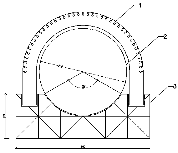
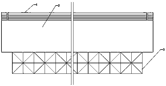
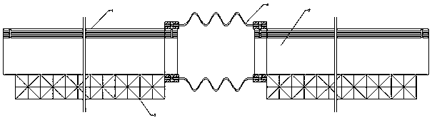
[0039] When the active underground high-efficiency integral suction and drainage blind pipe is used, it is installed on both sides of the lower part of the railway (highway) roadbed. After the excavation of the roadbed is completed, a 100mm thick coarse sand leveling layer is laid longitudinally at the designed blind ditch position on both sides of the bottom of the roadbed foundation. , and then placed in the active underground high-efficiency integral suction and drainage blind pipe system, and the two sections are connected by flexible joints. When the active underground high-efficiency integral suction and drainage blind pipe system is installed, an integral water collection inspection well is installed every 200 meters . The active underground high-efficiency integral suction and drainage blind pipes on both sides of the water collection inspection well are sloped 0.5% in the direction of the water collection inspection well, and ordinary PVC pipes are installed at the thi...


PUM


Abstract

The invention discloses an active type underground efficient water suction and drainage blind tube system. The active type underground efficient water suction and drainage blind tube system comprisesa water collecting inspection well, active type efficient water suction and drainage tube assemblies and a flexible joint, wherein the two sides of the water collecting inspection well are connected with the active type efficient water suction and drainage tube assemblies; the third surface of the water collecting inspection well is connected with an outlet tube; the flexible joint is used for connecting the two sections of the active type efficient water suction and drainage tube assemblies; each active type efficient water suction and drainage tube assembly consists of a base, a water drainage base, and an active type water suction plate, wherein the base, the water drainage tube and the active type water suction plate are connected through a heat-melting way, the base, the water drainage tube and the active type water suction plate are made of a high-strength engineering PVC material, so that anti-pressure ability and plastic mechanical properties are very good; and the flexible joint can be suitable for uneven local settling of various foundations, and can realize small-angle rotation in any direction. Active type water suction plates delicately improve single passive water seepage to active water drainage, so that water drainage efficiency is greatly improved.

Description

technical field [0001] The invention relates to an underground drainage system, in particular to an active underground high-efficiency drainage system. Background technique [0002] Due to the infiltration of natural precipitation and the rise of groundwater level, the water content of railway and road subgrades exceeds the design requirements of the subgrade, resulting in liquefaction of the subgrade, road subgrade muddying, subsidence, subsidence and other road diseases. ills. [0003] In order to solve the problems caused by groundwater problems in the subgrade, the design of open drainage ditches on both sides of the road was also adopted. However, this design of open ditch can only solve the problem of ground surface water, and cannot solve the problems of surface water seepage and underground water development. . [0004] With the rapid development of high-speed railways, the prevention and control of railway subgrade diseases has become an urgent situation. The rail...

Claims


Application Information

Patent Timeline
Patent Type & Authority Applications(China)
IPC IPC(8): E02D3/10
CPCE02D3/10E02D2300/0007
Inventor 刘亚丁田璐
Owner 刘亚丁
Why Eureka
Try Eureka