Helical hybrid stent

a hybrid stent and helical technology, applied in the field of stents, can solve the problems of increasing the trauma of the vessel at the end of the stent, affecting the natural tendency of the vessel to bend and stretch, and stents with good flexibility often lack sufficient and/or uniform radial support for the vessel wall, so as to enhance the flexibility of the loop or turn, enhance the coverage of the lumen without losing the overall flexibility of the stent, and minimize the space between

Active Publication Date: 2010-10-28
MEDINOL LTD
View PDF151 Cites 21 Cited by
  • Summary
  • Abstract
  • Description
  • Claims
  • Application Information

AI Technical Summary

Benefits of technology

[0011]In one embodiment of the invention, the main stent component may have one or more struts, which are sufficiently wide to include one or more full or partial fenestrations. The fenestrated struts may be connected by loops or turns whose width is narrower than that of the fenestrated struts to provide enhanced flexibility in the loops or turns.
[0012]In another embodiment, the main stent component may be designed such that each helical winding is nestled next to an adjacent helical winding of the helical structure so that the space between the windings is minimized; that is, one winding is nestled into an adjacent, substantially similar winding as the side band ribbon travels diagonally around the circumference of the stent. In this manner, the helical windings of the stent provide enhanced coverage of the wall of the...

Problems solved by technology

When the stent is more longitudinally stiff than the vessel in which it is implanted, increased trauma to the vessel may occur at the ends of the stent, due to stress concentrations on account of the mismatch in compliance between the stented and un-stented sections of the vessel, or otherwise.
In addition, the stent may interfere with the vessel's natural tendency ...

Method used


Image

  • Helical hybrid stent
  • Helical hybrid stent
  • Helical hybrid stent

Examples


Embodiment Construction

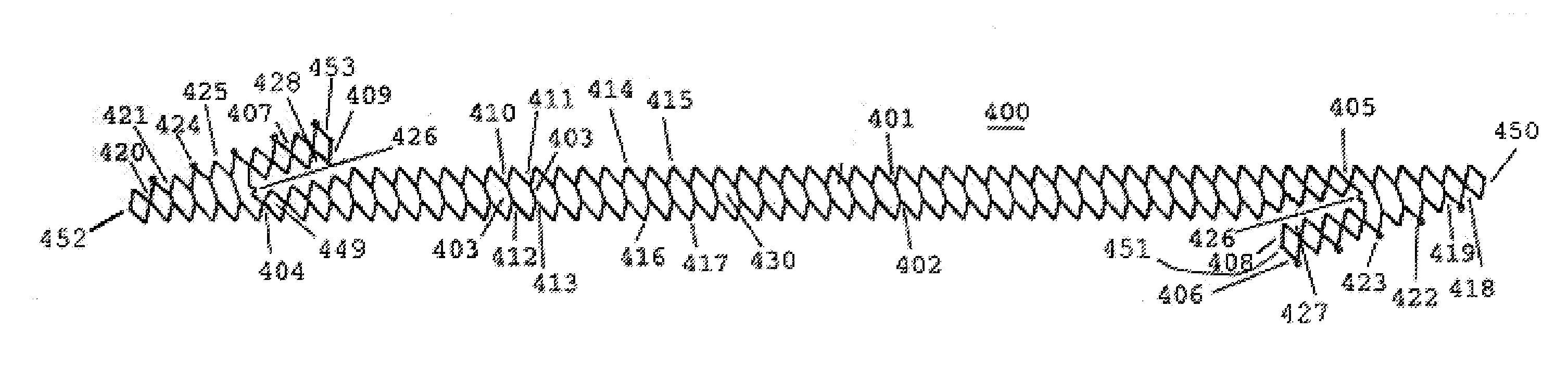
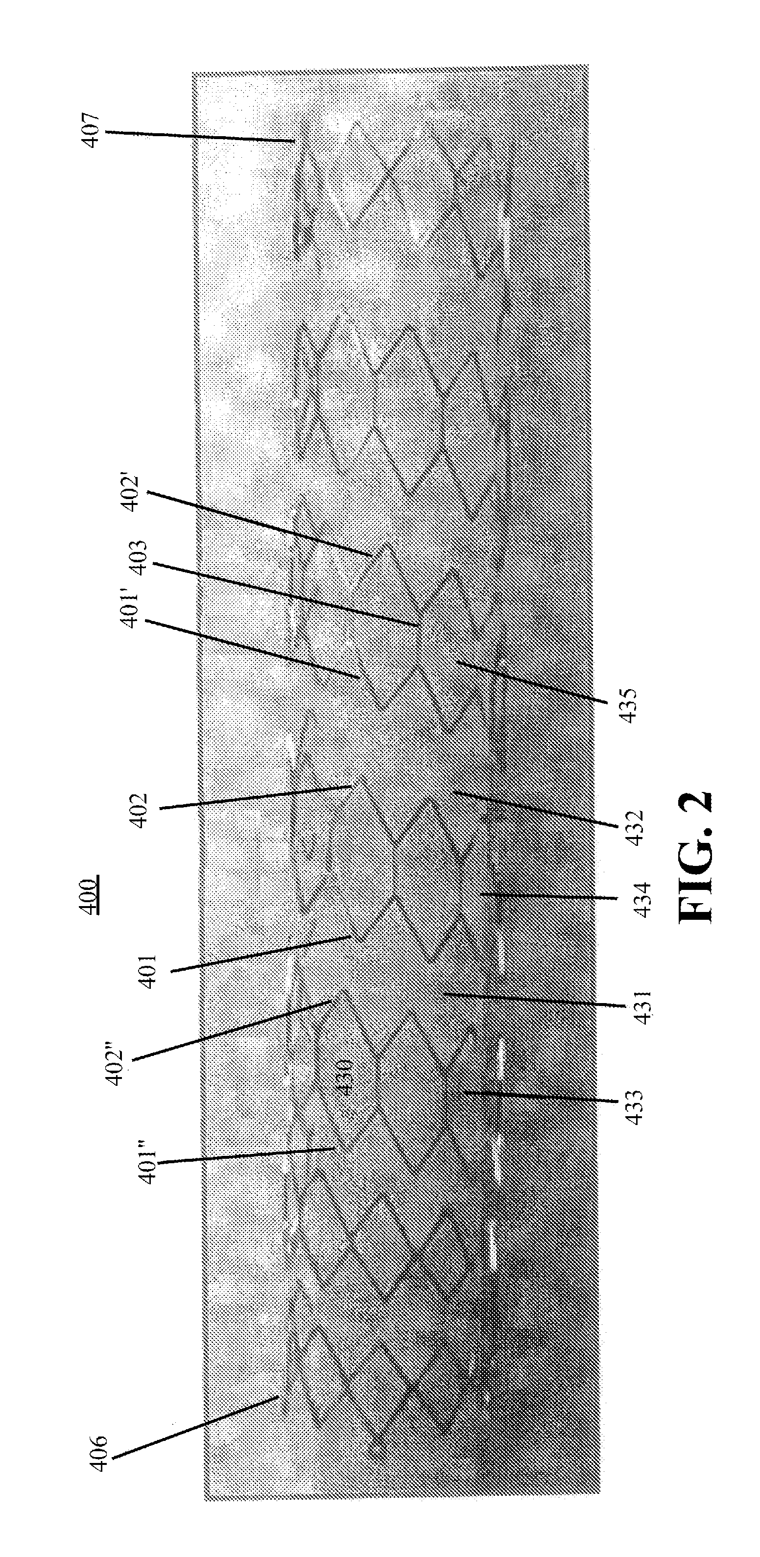
[0026]This invention provides a new class of intraluminal prosthetic devices defined as helical hybrid stents. As further explained below, the stents of the invention comprise a main stent component in the form of a helical tubular structure, which may be held in the tubular shape by a second stent component, i.e., a securement. The main stent component is formed from a continuous undulating or patterned strip helically wound to form a helical stent. The strip has end sections that form cylindrical rings in the tubular helical stent. As such, one inventive feature is the central body of the stent having a spiral structure which is flanked by cylindrical rings at both ends of the stent. The strip forming the central body portion comprises one or more side bands each having undulations while the ends sections comprise one or more end bands each having undulations. Each end band is connected to a side band at an angle offset to the side band and may extend back toward the side band. Th...


PUM

PropertyMeasurementUnit
Lengthaaaaaaaaaa
Angleaaaaaaaaaa
Structureaaaaaaaaaa

Abstract

An expandable helical stent is provided, wherein the stent may be formed of a main stent component and a securement. The main stent component is formed from a flat strip having one or more undulating side bands that may be connected to form geometrically shaped cells and are helically wound to form a stent. The helical coils of the main stent component may be spaced apart or nestled to each other. The nestling of the undulation of adjacent helical windings contributes to maintaining the tubular shape and uniformity of the helically coiled stent. Alternatively, the flat strip may comprise a single undulating pattern. At the ends of the main stent component are end bands, which when wound, form a cylindrical ring. In one embodiment, one or more struts of the main stent component may have a width sufficient to include one or more fenestrations. The fenestrated struts may be connected by loops or turns wherein the material is narrower than that of the fenestrated struts to provide enhanced flexibility. The helical tubular is maintained with a securement.

Description

[0001]This application claims the benefit of U.S. application Ser. No. 12 / 428,347, filed on Apr. 22, 2009, the entire content of which is incorporated by reference.FIELD OF THE INVENTION[0002]The invention relates generally to stents, which are intraluminal endoprosthesis devices implanted into vessels within the body, such as blood vessels, to support and hold open the vessels, or to secure and support other endoprostheses in vessels.BACKGROUND OF THE INVENTION[0003]Various stents are known in the art. Typically, stents are generally tubular in shape, and are expandable from a relatively small, unexpanded diameter to a larger, expanded diameter. For implantation, the stent is typically mounted on the end of a catheter with the stent being held on the catheter in its relatively small, unexpanded diameter. Using a catheter, the unexpanded stent is directed through the lumen to the intended implantation site. Once the stent is at the intended implantation site, it is expanded, typical...

Claims


Application Information

Patent Timeline
IPC IPC(8): A61F2/86A61F2/82B21D31/00
CPCA61F2/88A61F2/91A61F2250/0068A61F2220/0058A61L31/16A61F2220/005A61L31/022
Inventor RICHTER, JACOB
Owner MEDINOL LTD
Why Eureka
Try Eureka