Electric machine

a technology of electric machines and brushes, applied in the direction of dynamo-electric machines, rotary current collectors, electrical equipment, etc., can solve the problems of inability to maintain the correct operation temperature, the electrical performance of brushes and their deterioration (wear) is decaying in an unacceptable manner, and the electric machine is quickly worn. , to achieve the effect of high reliability and low cost of manufactur

Inactive Publication Date: 2010-11-04
SPAL AUTOMOTIVE
View PDF10 Cites 14 Cited by
  • Summary
  • Abstract
  • Description
  • Claims
  • Application Information

AI Technical Summary

Benefits of technology

[0014]One aim of the present invention is to provide an electric machine with a high level of reliability.
[0015]Another aim of the invention is to provide an electric machine which is inexpensive to manufacture.

Problems solved by technology

This seriously penalises the heat dispersion of the brushes, which therefore tend to overheat, reaching unacceptable temperatures for their correct operation.
It has actually been found that the materials ordinarily used on a large scale to manufacture the brushes have wear resistance and electrical conductivity properties which remain at acceptable levels up to temperatures which are much lower than those reached in sealed electric motors and in particular these properties are maintained for temperatures up to approximately 150° C. When this limit has been exceeded, the decay of the electrical performance of the brushes as well as their deterioration (wear) increases in an unacceptable manner, and this leads to rapid wear of the electric machine which, after a short time, must be replaced or undergo maintenance.
Where the brush holder element is made of plastic material, the negative effect of the temperature increase is even more penalising due to the very poor heat exchange properties of the plastic materials.
Disadvantageously, the above-mentioned over sizing has a negative influence both on the dimensional aspects of the electric machine, making it larger, and on the manufacturing cost of the machine itself.

Method used


Image

  • Electric machine
  • Electric machine
  • Electric machine

Examples


Embodiment Construction

[0026]The electric machine described in detail below is specifically an electric motor. However, the technical characteristics and the teachings of the present invention also apply to other rotary electric machines of the brush-commutator type, in particular to electricity generators.

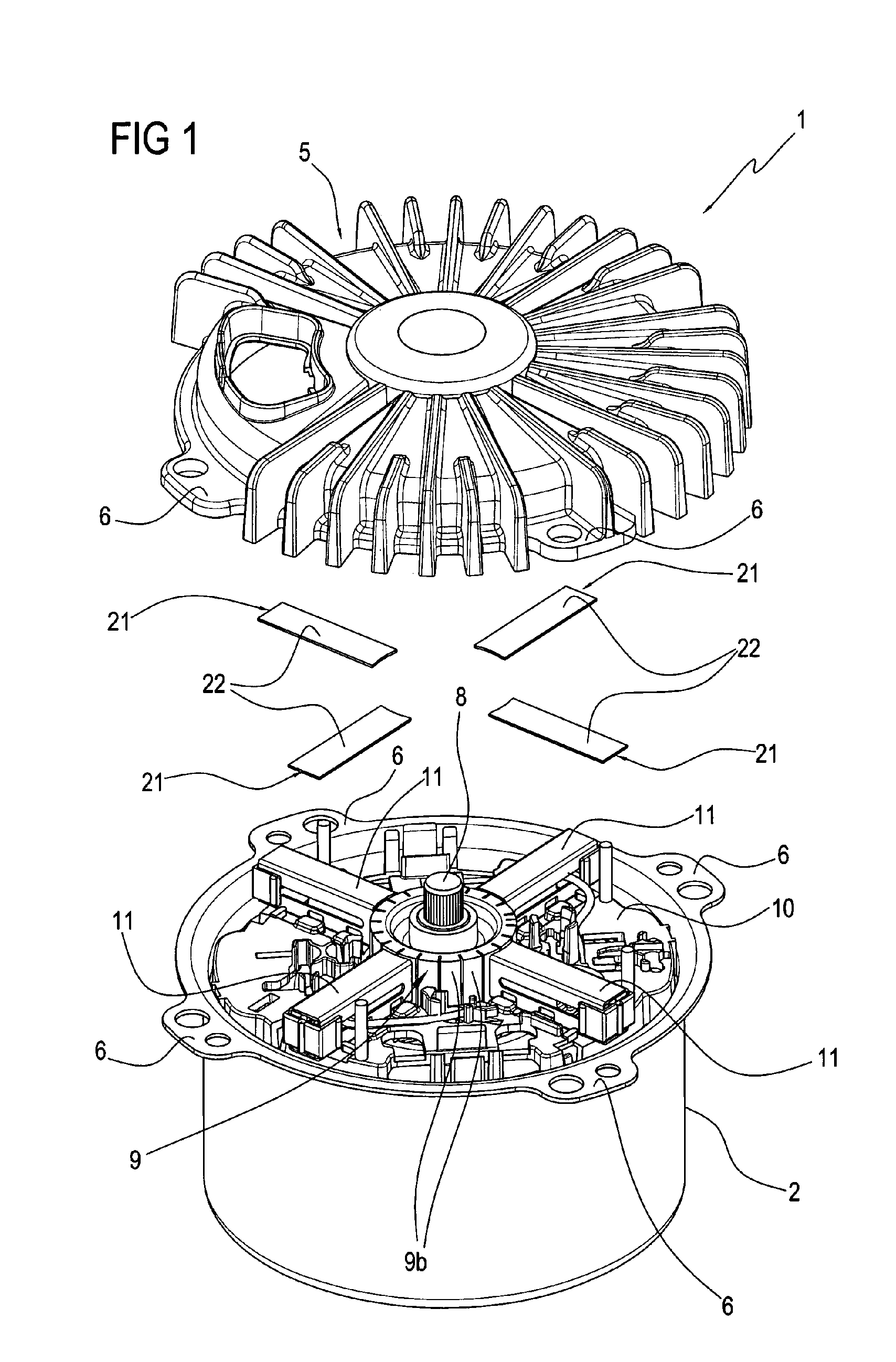
[0027]With reference to the accompanying drawings, the numeral 1 denotes in its entirety an electric motor according to the present invention.

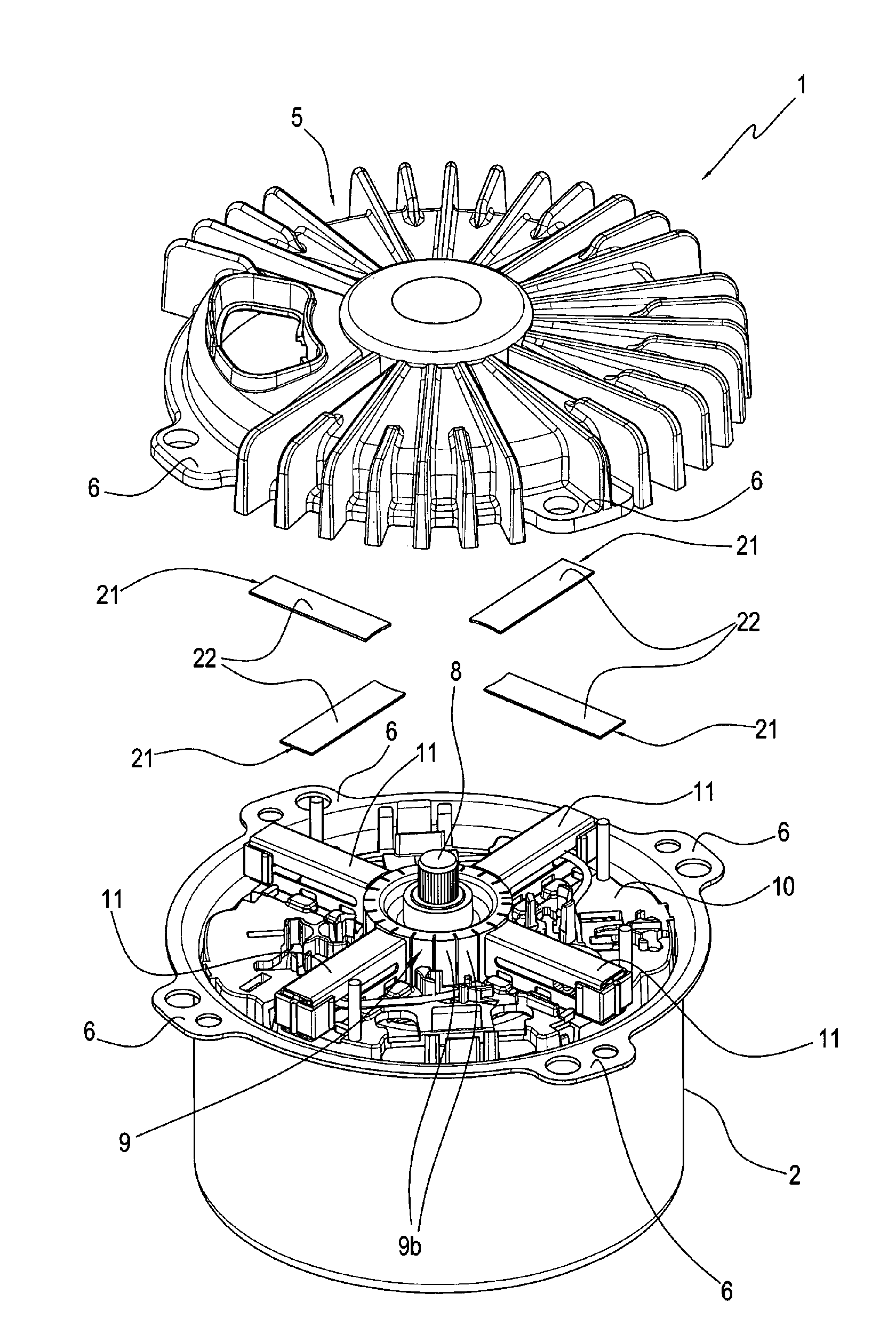
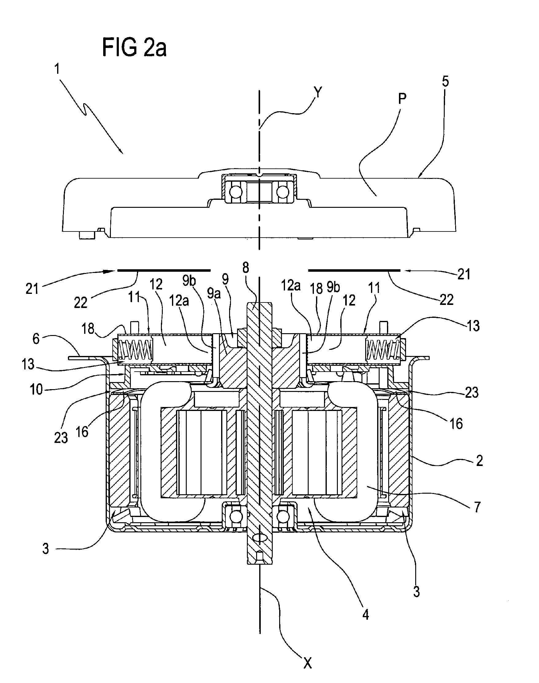
[0028]The electric motor 1 comprises a casing 2, inside of which are housed a stator 3 and a rotor 4, and a covering element 5 or cover which is permanently associated with the casing 2 by the joints of special flanges 6 formed on the casing 2 and on the covering element 5.

[0029]In an assembled configuration of the motor 1, the casing 2, the stator 3 and the rotor 4 extend around a single axis coinciding with the axis of rotation “X” of the rotor 4.

[0030]The rotor 4 has at least one winding obtained by winding a lead wire around a polar expansion of the rotor 4 ac...


PUM


Abstract

An electric machine comprises: a casing (2); a stator (3) and a rotor (4) supported by the casing (2), the rotor (4) having at least one rotor winding (7); a commutator (9) connected permanently to the rotor (4) and electrically connected to the rotor winding (7); a pair of brushes (12), each having a first end (12a) maintained in a sliding position with the commutator (9) and electrically connected to respective terminals which may be connected to an electricity mains supply; a pair of brush holder elements (11) supported by the casing (2), each brush holder element (11) being associated with a respective brush (12) to keep it pressed on the commutator (9). Each brush holder element (11) has at least one lateral surface (18) to face a respective butting position (17) of the casing (2), and which may be joined to the butting portion (17) to transmit a thermal power to the butting portion. The lateral surface (18) of each brush holder element (11) is electrically isolated from the respective butting portion (17).

Description

CROSS-REFERENCE TO RELATED APPLICATIONS[0001]This application is the National Phase of International Application PCT / IB2008 / 002018 filed Jul. 23, 2008 which designated the U.S. and that International Application was published under PCT Article 21(2) in English.[0002]This application claims priority to Italian Patent Application No. BO2007A000575 filed Aug. 7, 2007, and PCT Application No. PCT / IB2008 / 002018 filed Jul. 23, 2008, which applications are incorporated by reference herein.TECHNICAL FIELD[0003]This invention relates to an electric machine.[0004]In particular, the invention relates to a rotary electric machine of the commutator type, and, even more specifically, a sealed electric machine, for example a motor of the type used to drive an electric cooling fan for automotive applications or an electricity generator. Preferably, the electric machine according to this invention is of the type powered with direct current.BACKGROUND ART[0005]Prior art commutator type electric machi...

Claims


Application Information

Patent Timeline
Patent Type & Authority Applications(United States)
IPC IPC(8): H01R39/38H02K5/18
CPCH02K5/148H01R39/46
Inventor DE FILIPPIS, PIETRO
Owner SPAL AUTOMOTIVE
Why Eureka
Try Eureka