Display device and illumination device

a technology of illumination device and display device, which is applied in the field of display device and illumination device, can solve the problems of low efficiency, small gamut, and inability to easily allow a 2d dimming of backlight, and achieve the effects of reducing overlap, boosting capability, and improving color uniformity

Inactive Publication Date: 2010-11-04
KONINKLIJKE PHILIPS ELECTRONICS NV
View PDF10 Cites 31 Cited by
  • Summary
  • Abstract
  • Description
  • Claims
  • Application Information

AI Technical Summary

Benefits of technology

[0027]In prior art LCD backlight illumination devices comprising separate color emitting light sources (e.g. red, green and blue LEDs) that require mixing of the different colors outside the light emitters to create a uniform color point across the exit window of the backlight illumination device, the finite overlap between the luminance patterns of the light sources causes color point deviations in the exit window of the backlight illumination device when locally dimming or boosting one or more light emitters. Unlike some of the prior art LCD backlight illumination devices which use separate blue, red and green sources, the (backlight) illumination device of the invention allows in this way a local dimming of the (backlight) illumination device, with decreased overlap between the luminance patterns associated with the individual or groups of individual LED packages which enables deeper local dimming than what is possible with a larger overlap between the mentioned luminance patterns, and without substantially affecting the color point distribution of the (backlight) illumination device. Therefore, with the (backlight) illumination device of the invention, 2D dimming and / or boosting may be possible.
[0028]As a further aspect of the invention, also 1D dimming or boosting capability may be improved with the (backlight) illumination device of the invention, both in “direct lit” and in “edge lit” (backlighting) configurations, thanks to the improved color uniformity.

Problems solved by technology

A disadvantage of the prior art systems may be that they do not easily allow a 2D dimming of the backlight, i.e. a reduction of the intensity of the backlight at a specific part of the backlight, whereas the ability of local dimming is an advantageous and desired property for backlights.
A further disadvantage of prior art systems may be their relative low efficiency and / or small gamut.

Method used


Image

  • Display device and illumination device
  • Display device and illumination device
  • Display device and illumination device

Examples


Embodiment Construction

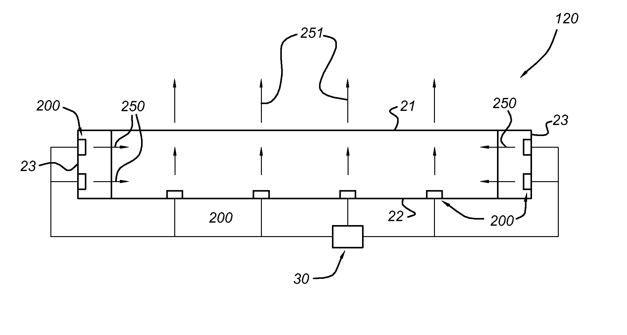
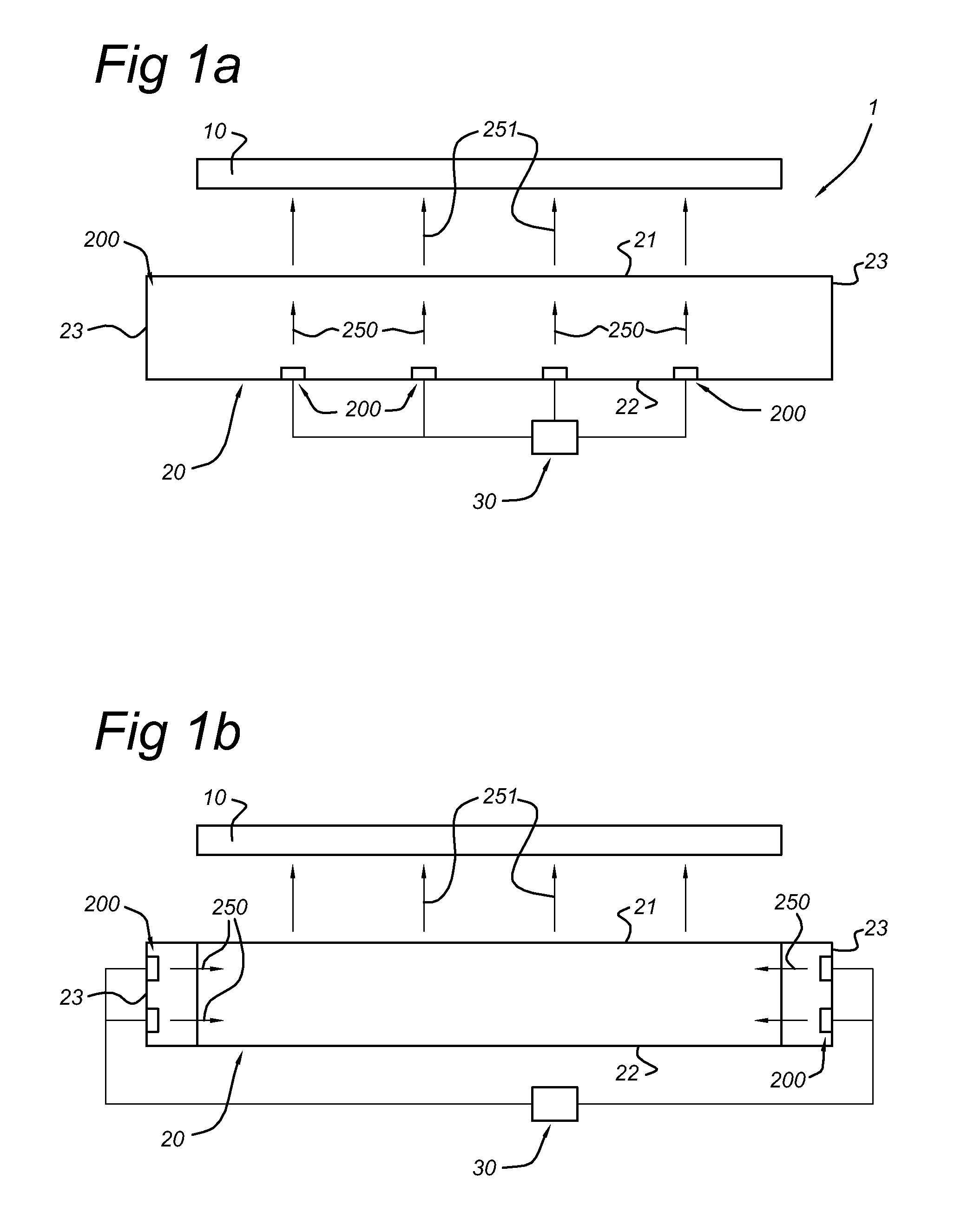
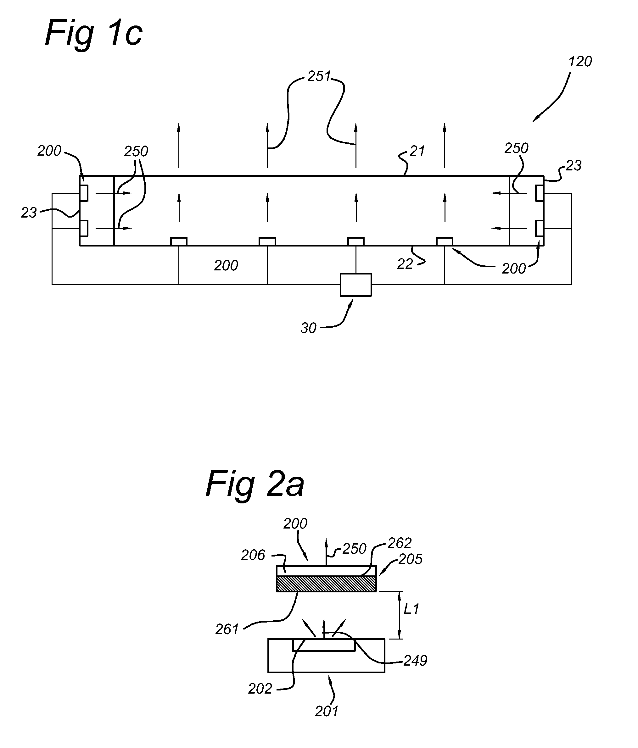
[0084]FIGS. 1a and 1b schematically depict embodiments of a LCD display device 1 with a back light illumination device 20, arranged to backlight an LCD display 10. Optional intermediate layers, such as optical filters, diffusers, brightness enhancement films, polarizers, etc., known to the person skilled in the art, are not indicated in this schematic drawing. The backlight illumination device 20 may generate white light 251 for backlighting the LCD display 10. The back light illumination device 20 comprises an exit window 21, arranged to allow light 250 generated in the backlight illumination device 20 escapes therefrom and illuminate the LCD display 10. The (backlight) illumination device 20 comprises one or more LED packages 200, especially a plurality of LED packages 200, such as in the order of 1-20, like 2-20 (for small LCD panels, e.g. for mobile applications), 4-50 (for medium size panels, e.g. for automotive centre console LCD panels), or 20-1000 (for large panels, e.g. LCD...


PUM

PropertyMeasurementUnit
emission wavelengthaaaaaaaaaa

Abstract

The invention especially provides a display device (1) with a liquid crystal display (LCD) panel (10) and a backlight illumination device (20), wherein the backlight illumination device (20) comprises a light emitting diode package (200) arranged to generate white backlight (251), wherein the light emitting diode package (200) comprises a blue light emitting diode, LED (201), a green luminescent material (203) and a red luminescent material (204); and a transmissive ceramic layer (206), arranged to transmit at least part of the blue emission (249), wherein the transmissive ceramic layer (206) comprises at least part of the green luminescent.material (203) and/or the red luminescent material (204). The LED (201), the green luminescent material (203) and the red luminescent material (204) are arranged to generate white light (250) for backlighting the liquid crystal display panel (10).

Description

FIELD OF THE INVENTION[0001]The invention relates to a display device comprising a liquid crystal display (LCD) panel and a backlight illumination device arranged to backlight the LCD panel, wherein the backlight illumination device comprises a light emitting diode package. The invention further relates to an illumination device comprising a light emitting diode package, especially a plurality of light emitting diode packages, arranged to emit light.BACKGROUND OF THE INVENTION[0002]LCD panels with backlight illumination devices (shortly also indicated with “backlight” or “backlight unit” or “backlight device”) are known in the art. U.S. Pat. No. 7,052,152 for instance describes a display device comprising a housing comprising reflective surfaces and a top opening through which light is emitted for backlighting a liquid crystal display panel; an array of substantially identical light emitting diodes (LEDs) supported on a reflective bottom surface in the housing, each LED emitting lig...

Claims


Application Information

Patent Timeline
Patent Type & Authority Applications(United States)
IPC IPC(8): G02F1/13357
CPCC04B35/44C04B35/597C04B2235/3208C04B2235/3213C04B2235/3224C04B2235/3225Y02B20/181C04B2235/764C09K11/7734C09K11/7774G02F1/133603G02F2001/133614H01L33/504C04B2235/3229Y02B20/00G02F1/133614C09K11/77347C09K11/77348
Inventor HOELEN, CHRISTOPH GERARD AUGUSTPEETERS, MARTINUS PETRUS JOSEPHBOEREKAMP, JACOBUS GERARDUS
Owner KONINKLIJKE PHILIPS ELECTRONICS NV
Why Eureka
Try Eureka