Turbine with variable number of nozzles

a turbine and variable technology, applied in the direction of valve drives, combustion air/fuel air treatment, liquid fuel engines, etc., can solve the problems of large fluctuations in the amount of gas emitted from the engine, low fuel economy, and substantial deterioration of the efficiency of the gas turbine in the range outside the design gas pressure and flow rate, so as to achieve high efficiency and high degree of freedom , the effect of increasing the efficiency of the turbin

Inactive Publication Date: 2010-11-04
JOHO CORP
View PDF9 Cites 10 Cited by
  • Summary
  • Abstract
  • Description
  • Claims
  • Application Information

AI Technical Summary

Benefits of technology

[0009]The first means for solving problems according to the present invention provides a gas turbine comprising: a plurality of rotor blades; a plurality of nozzles injecting gas to said plurality of rotor blades, each of said plurality of nozzles including an inlet port, each of a plurality of said inlet ports being circumferentially arranged so as to be grouped with at least one other inlet port into a group; and an opening and closing valve disposed over said plurality of inlet ports so as to be commonly functioned therefore, said opening and closing valve being rotated to vary number of said plurality of nozzles to actuate thereof. The gas turbine according to the first means for solving problems is hereinafter referred to as “variable nozzle number turbine”.
[0010]The variable nozzle number turbine varies number of nozzles to be actuated so as to change total area of nozzle openings, thereby addressing fluctuation of amount of gas. Since the nozzles themselves are fixedly arranged, the relationship between circumferential velocity and inlet angle and outlet angle of rotor blades is constant at stable rotational speed of the turbine, resulting in high efficiency secured even when amount of gas varies. This provides an advantage of increasing efficiency thereof in partial load conditions when compared with conventional variable nozzle turbines. The variable nozzle turbine has another advantage due to high degree of freedom in nozzle configuration: capable of forming convergent nozzle for achieving sonic velocity or higher and securing high rigidity against a shock wave generated by fluid with the sonic velocity. This enables the turbine to effectively convert exhaust energy into motive power even when using one-stage turbine at high pressure. Opening and closing of the nozzles can be done using an opening and closing valve that rotates about a turbine shaft. This feature can be realized with minimum increase of the number of heat-resistant parts. The sealing surface of the opening and closing valve is configured with a simple surface with the center aligned with the turbine shaft. This provides a further advantage of easily maintaining sealing property thereof against thermal strains.
[0011]The variable nozzle number turbine has a benefit of increasing its efficiency under partial load conditions when it is used for a gas turbine engine whose load tends to fluctuates. The variable nozzle turbine may be used as an exhaust gas turbine with a displacement engine such as a two-stroke cycle engine, a four-stroke cycle engine and a six-stroke cycle engine. Such use enables the variable nozzle turbine to effectively extract motive power to outside under low load conditions which are frequently used. This provides an advantage of enabling a turbocharger to generate electric power for a vehicle, which has not been realized so far.
[0012]In view of adhesion, the nozzle opening and closing valve is preferably made of material different from material of which the turbine housing is made. If the turbine housing is made of a heat-resistant alloy, the nozzle opening and closing valve is preferably made of a heat-resistant ceramics. In case of decreasing the number of nozzles, gas flow between rotor blades becomes discontinuous. In such a case, an impulse turbine or the like that has no pressure changes at rotor blades is preferably used.
[0013]The second means for solving problems according to the present prevention provides a multi-stage turbine comprising at least one gas turbine according to the first means for solving problems, said at least one gas turbine being configured in tandem with multiple stages, each of said at least one gas turbine including a mechanism for varying overall area of openings of said nozzles, said mechanism being independently operated for each of said at least one gas turbine.
[0014]The second means for solving problems according to the present prevention enables a gas turbine to employ high inflow pressure and address fluctuation of gas flow rate more effectively using a single-shaft turbine. A multiple-stage configuration enables a gas turbine to employ higher gas pressure even when using a gas flow with the sonic velocity or less: assuming that pressure ratio of outlet to inlet for each stage is 1.9, 3.6 atm. for two stages and 6.8 atm. for three stages can be employed, respectively.

Problems solved by technology

This causes large fluctuations in amount of gas emitted from an engine.
In particular, a gas turbine substantially deteriorates its efficiency in the range outside of designed gas pressure and flow rate.
This causes a gas turbine and an internal combustion engine with an exhaust gas turbine to deteriorate their efficiency under partial load conditions when they are used for vehicles, thus resulting in low fuel economy.

Method used


Image

  • Turbine with variable number of nozzles
  • Turbine with variable number of nozzles
  • Turbine with variable number of nozzles

Examples


first embodiment

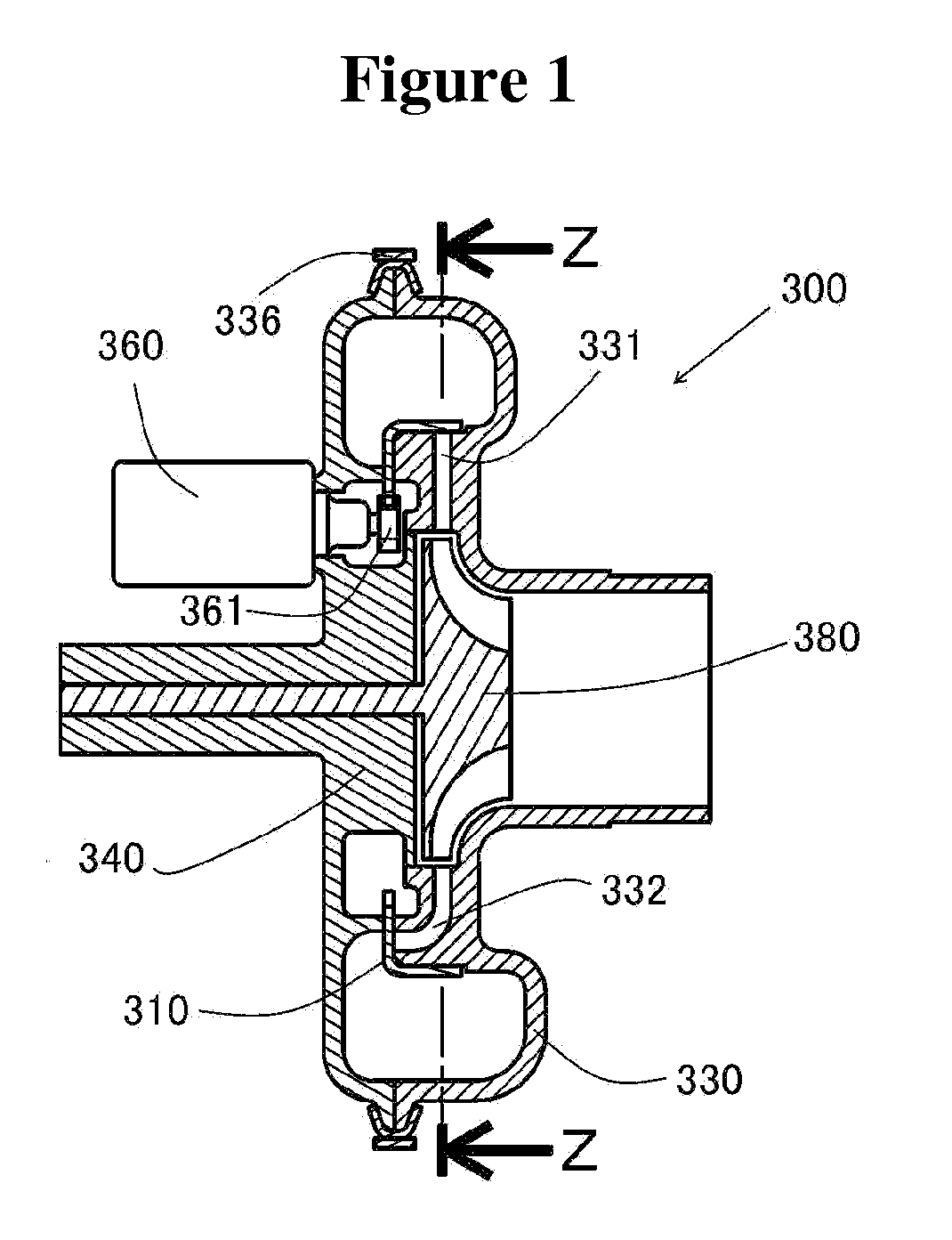
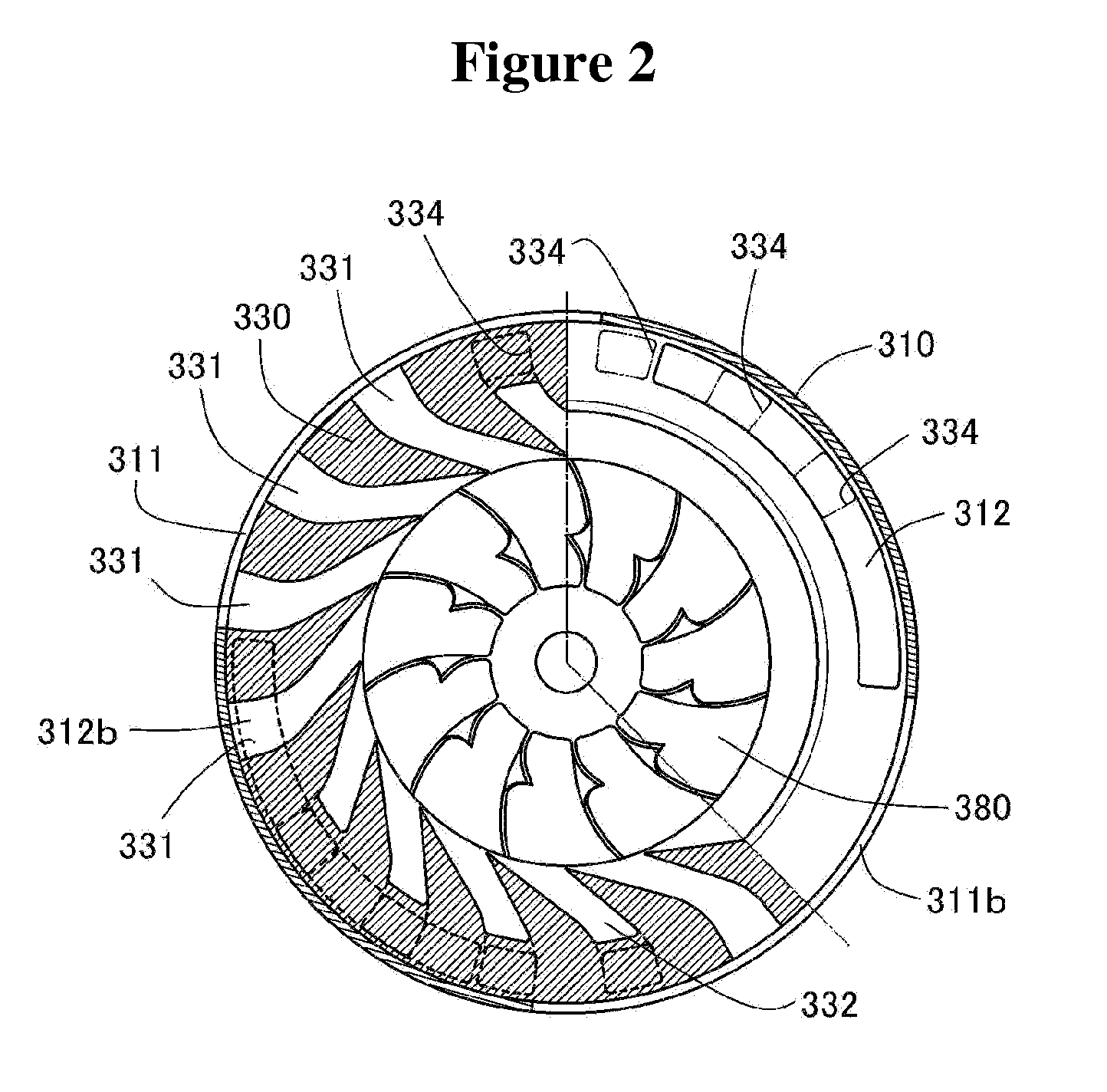
[0102]FIG. 1 illustrates a cross-sectional view of a scroll-type gas turbine 300 according to an embodiment of the present invention in accordance with the first means for solving problems. A nozzle opening and closing valve 310 includes a gear cut on the inner side thereof. The gear rotates by an external force via a drive gear 361 that is driven by a rotary actuator 360 to open and close the valve 310. In FIG. 1, nozzles 331 and 332 are illustrated in such a manner as displaced about the center of the valve. The nozzles are grouped into four groups. Each of the groups includes an opening arranged radially and axially in an alternate manner per 90 degrees and symmetrically about the center, thus comprising 16 nozzles in total. In the present embodiment, the nozzles are positioned symmetrically with respect to the center of the valve in order to balance loads applied to the valve; however, in order to achieve its primary function, they are not necessarily so positioned.

[0103]FIG. 2 ...

second embodiment

[0107]FIG. 3 illustrates a two-stage turbine 400 according to the second means for solving problems. The two-stage turbine 400 includes two axial flow turbines according to the first means for solving problems, in which the two axial flow turbines are coaxially installed. FIG. 3B is a cross-sectional view taken along the line Y-Y in FIG. 3A. Each of a nozzle opening and closing valve 410, 420 includes a gear cut thereon. The gear is driven by a rotary actuator 460, 470 via a drive gear 461, 471.

[0108]FIG. 3A is a front elevational view of the nozzle opening and closing valve 420 of the second stage turbine and the nozzle inlets disposed in a turbine housing 330 as seen from the left-hand side of the turbine in FIG. 3B. The elements 421, 421b, 422, 422b designate the openings of the nozzles and closing valve 420, through which nozzle inlets 441, 442 is seen. In this embodiment, the nozzle openings are all disposed on a disk surface. The nozzle opening and closing valve 420 is driven ...

third embodiment

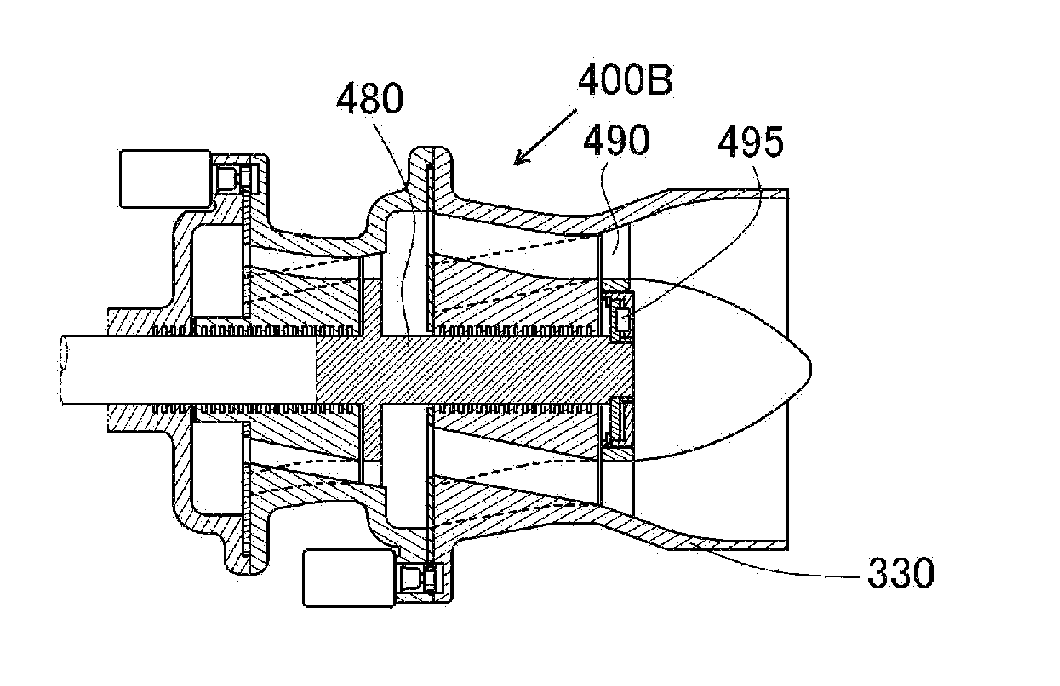
[0111]FIG. 5 illustrates a cross-sectional view of the second embodiment according to the second means for solving problems. The structure of the nozzle opening and closing valve is identical to those of the second embodiment as illustrated in FIG. 3. A second stage turbine 490 is rotatably connected to a first stage turbine via a one-way clutch 495, thus substantially constituting a dual shaft turbine. Upon the gas pressure at a collective inlet lowering sufficiently for the first stage turbine to receive the whole amount of pressure energy, the dual shaft turbine operates in such a manner that it fully opens an opening and closing valve of the second turbine to maximize the overall area of nozzle openings thereof so as to keep the velocity of gas flow at the nozzle outlet of the first stage turbine unchanged, thereby keeping the rotational speed of a main shaft 480 substantially constant. At this moment, the velocity of the gas injected by nozzles of the second stage turbine lower...


PUM


Abstract

A gas turbine generally exhibits a substantial deterioration in efficiency against fluctuation of gas flow rate. A variable nozzle turbine is a solution for this disadvantage; however, it has also another disadvantage of low efficiency under partial load conditions and a large number of heat-resistant moving components. A variable nozzle number turbine according to this invention overcomes these disadvantages. The turbine includes nozzles for injecting gas to rotor blades. The nozzles include inlet ports circumferentially arranged so as to be grouped into a group and an opening and closing valve disposed thereover so as to be commonly functioned therefore. This arrangement realizes a gas turbine with no deterioration of efficiency against fluctuation of gas inflow rate by only one heat-resistant moving component additionally installed. The variable nozzle number turbine according to this invention also realizes a turbine compressor with no surge limit when used as a regenerator. These turbines further realizes a small-sized gas turbine with improved fuel economy under partial load conditions and a turbocharger for regenerating electric power as well as improving efficiency of a displacement engine used therewith. It is to be noted that the inventor is ready for grant of working license.

Description

TECHNICAL FIELD[0001]The present invention relates to gas turbines having high efficiency for applications with a large fluctuation in amount of gas inflowing thereto and its use.BACKGROUND ART[0002]A gas turbine has excellent features such as its compactness, high efficiency, low frictions due to no reciprocating portion, and durability to high temperatures due to no sliding portion except bearings. These features cause a gas turbine to be often used as an exhaust gas turbine that converts pressure energy remaining in exhaust gas emitted from a displacement engine into motive power.[0003]However, rotational speed and load of an engine, when it is used for vehicles such as automobiles, greatly vary depending on operating conditions such as acceleration of a vehicle and slope of roads. This causes large fluctuations in amount of gas emitted from an engine. In particular, a gas turbine substantially deteriorates its efficiency in the range outside of designed gas pressure and flow rat...

Claims


Application Information

Patent Timeline
Patent Type & Authority Applications(United States)
IPC IPC(8): F04D27/02F01D17/12
CPCF01L1/08F01L1/38F02B75/021F02B2031/006F02M25/0711Y02T10/142F02M25/0727F02M35/10203F02M35/10222F02M35/1085F02M25/072F02M26/08F02M26/17F02M26/23Y02T10/12F02B25/26F02B41/10F02B63/04F02B75/02
Inventor OOYAMA, KAZOU
Owner JOHO CORP
Why Eureka
Try Eureka