Method and apparatus for monitoring an organ of a patient

a technology for monitoring organs and patients, applied in the direction of catheters, angiography, therapy, etc., can solve the problems of limited conductance technique, less robust measurement, and no proposed technology for chronic left ventricular volume measurements

Active Publication Date: 2010-11-04
BOARD OF RGT THE UNIV OF TEXAS SYST
View PDF2 Cites 62 Cited by
  • Summary
  • Abstract
  • Description
  • Claims
  • Application Information

AI Technical Summary

Benefits of technology

[0041]FIG. 8 shows that the LV epicardial admittance technique can also provide the identical real-time LV dimension or distance as short axis

Problems solved by technology

There are currently no proposed technologies that can perform chronic left ventricular volume measurements in part because implanted devices in the left heart lead to arterial embolism and stroke.
Further, the conductance technique is limited as the resulting volume measured is a combination of both blood and surrounding myocardium, while only the blood volume is desired.
Further, as the LV fails, it will remodel to accommodate the increased load, to reduce chamber pressures.
However, there are many concerns regarding using right heart pressures to monitor for impending heart failure.
The major concern is that right heart failure is downstream of left heart failure and pulmonary edema, and based on physiologic principles, will be a less robust measure.
Second, the device was reviewed by the FDA in February 2007, and approval was not granted based on the COMPASS-HF study due to statistically non-significant results between right heart pressure and control arms.
Third, the device requires correction for varying ambient atmospheric pressure with an external device that records am

Method used


Image

  • Method and apparatus for monitoring an organ of a patient
  • Method and apparatus for monitoring an organ of a patient
  • Method and apparatus for monitoring an organ of a patient

Examples


Embodiment Construction

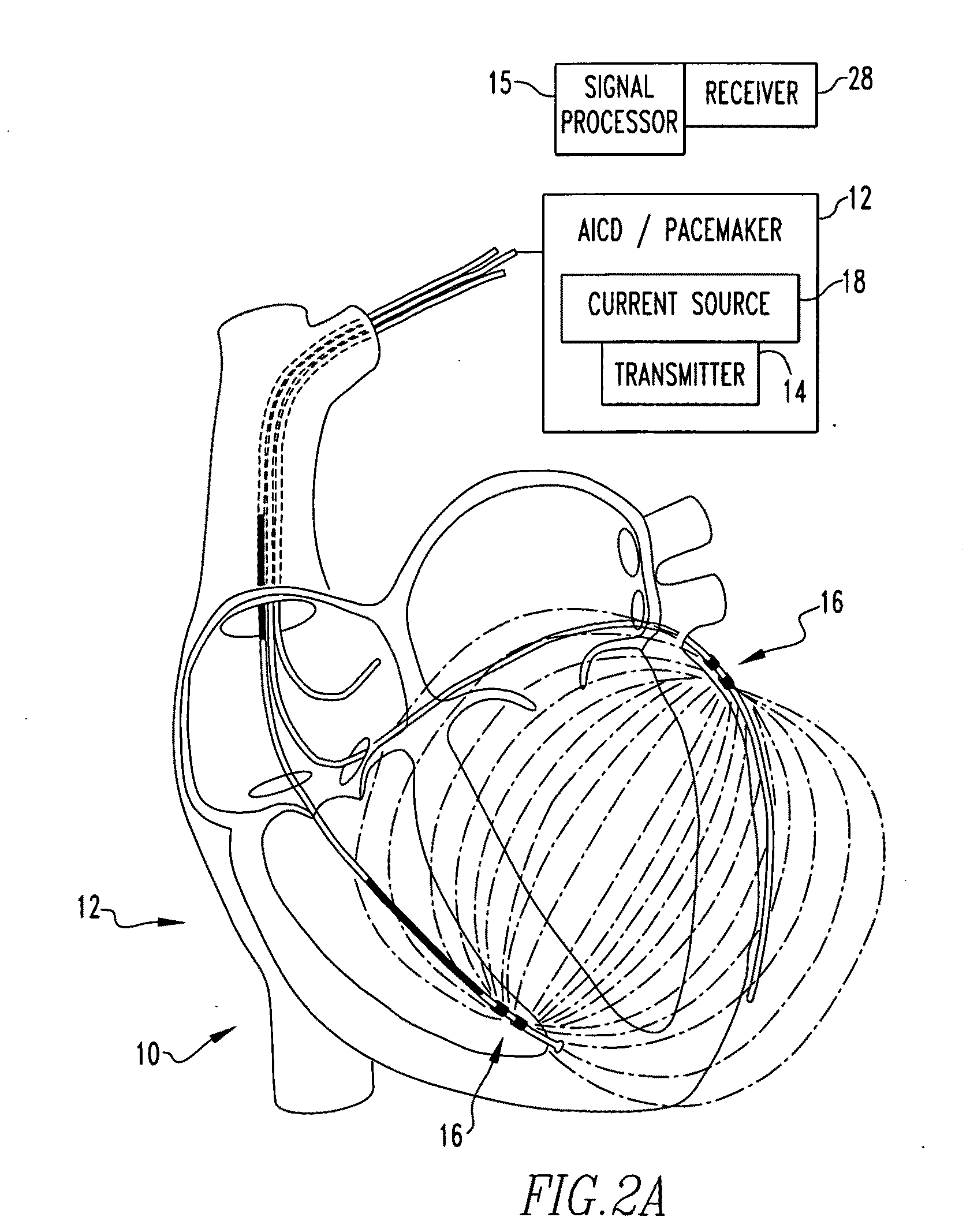
[0065]Referring now to the drawings wherein like reference numerals refer to similar or identical parts throughout the several views, and more specifically to FIGS. 2a and 2b thereof, there is shown an apparatus 10 for determining tissue versus fluid components of an organ. The apparatus 10 comprises a detector 12 that generates a detector signal based on electrical signals derived from tissue and fluid. The apparatus 10 comprises a signal processor 15 in communication with the detector 12 which subtracts in real time a tissue component from the detector signal and produces a fluid volume signal.

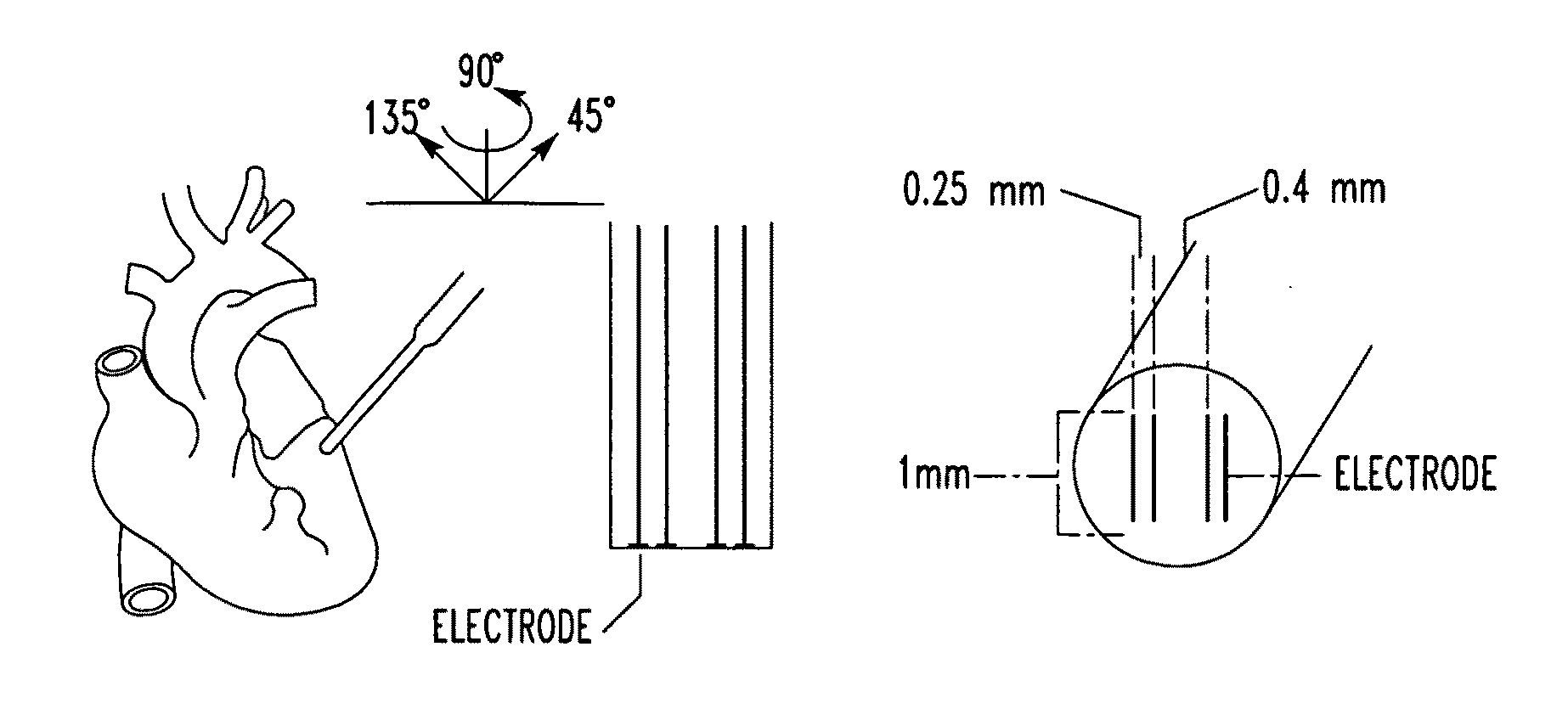
[0066]The detector 12 may include a plurality of electrodes 16 adapted to contact the organ that produce a combined signal that has the tissue component and a fluid component. The electrodes 16 may have a varying distance between them and the processor 15 determines organ surface admittance based on the vary distance between the electrodes 16. The organ may be a heart, the fluid is blood, th...


PUM


Abstract

An apparatus for determining tissue versus fluid components of an organ include a detector that generates a detector signal based on electrical signals derived from tissue and fluid. The apparatus includes a signal processor in communication with the detector which subtracts in real time a tissue component from the detector signal and produces a fluid volume signal. A method for monitoring a patient's fluid volume of a patient's organ. An apparatus for monitoring a patient's organ. A method for monitoring a patient's organ. A method to piggyback an admittance system onto a AICD/Bi-ventricular Pacemaker for a heart of a patient, in particular a weakened heart having features consistent with congestive heart failure. An apparatus for monitoring an organ, such as a heart, lungs, brain, skeletal muscle, and bladder of a patient which includes a detector which detects the admittance of the organ. The apparatus includes a transmitter in communication with the detector which transmits a wireless signal indicative of the admittance of the organ. A method for monitoring an organ of a patient includes the steps of detecting with a detector the admittance of the organ. There is the step of transmitting with a transmitter in communication with the detector a wireless signal indicative of admittance of the organ.

Description

CROSS-REFERENCE TO RELATED APPLICATIONS[0001]This is a continuation-in-part application of U.S. patent application Ser. No. 12 / 086,040 filed Jun. 4, 2008, which is a 371 of international application PCT / US2006 / 47649 filed Dec. 14, 2006, which is an international application of U.S. provisional application Ser. No. 60 / 753,105 filed Dec. 22, 2005, all of which are incorporated by reference herein.FIELD OF THE INVENTION[0002]The present invention is related to determining tissue versus fluid components of an organ. (As used herein, references to the “present invention” or “invention” relate to exemplary embodiments and not necessarily to every embodiment encompassed by the appended claims.) More specifically, the present invention is related to determining tissue versus fluid components of an organ using electrodes having a varying inter-electrode distance to identify admittance. Moreover, the present invention is related to detecting a heart's volume or diameter via admittance of the ...

Claims


Application Information

Patent Timeline
IPC IPC(8): A61B5/0215A61B5/053A61B5/02A61B5/08A61N1/368
CPCA61B5/0031A61N1/3962A61B5/0535A61B5/0538A61B5/1076A61B5/204A61B5/441A61B5/4519A61B5/4878A61N1/36521A61N1/3684A61B5/029A61B5/0295A61B5/0452A61B5/0476A61B5/0488A61B5/0537A61B5/0809A61B5/0215A61N1/36843A61N1/39622A61B5/349A61B5/369A61B5/389
Inventor FELDMAN, MARC D.PORTERFIELD, JOHNRAGHAVAN, KARTHIKVALVANO, JONATHAN W.PEARCE, JOHN A.
Owner BOARD OF RGT THE UNIV OF TEXAS SYST
Why Eureka
Try Eureka