
Clock generating circuit of computer

Inactive Publication Date: 2010-11-04
HONG FU JIN PRECISION IND (SHENZHEN) CO LTD +1
View PDF18 Cites 2 Cited by
  • Summary
  • Abstract
  • Description
  • Claims
  • Application Information

AI Technical Summary

Benefits of technology

The present patent relates to a clock generating circuit for a computer. The circuit includes two phase-locked loop circuits and a register. The circuit generates clock signals for components of the computer, such as the central processing unit and data bus. The circuit ensures that the clock signals are stable and free from noise. The technical effect of the patent is to provide a reliable and efficient clock generating circuit for computers, which ensures that the clock signals are stable and free from noise. This improves the performance of the computer and prevents interference between components.

Problems solved by technology

Performance of the computers may be influenced if the clock generators are improperly designed.
For example, when a Bitland X1550 graphic card works with an Intel E4400 central processing unit in a computer, no image can be displayed, this problem is caused by a deficiently designed clock generator of the computer.

Method used


Image

  • Clock generating circuit of computer
  • Clock generating circuit of computer
  • Clock generating circuit of computer

Examples


Embodiment Construction

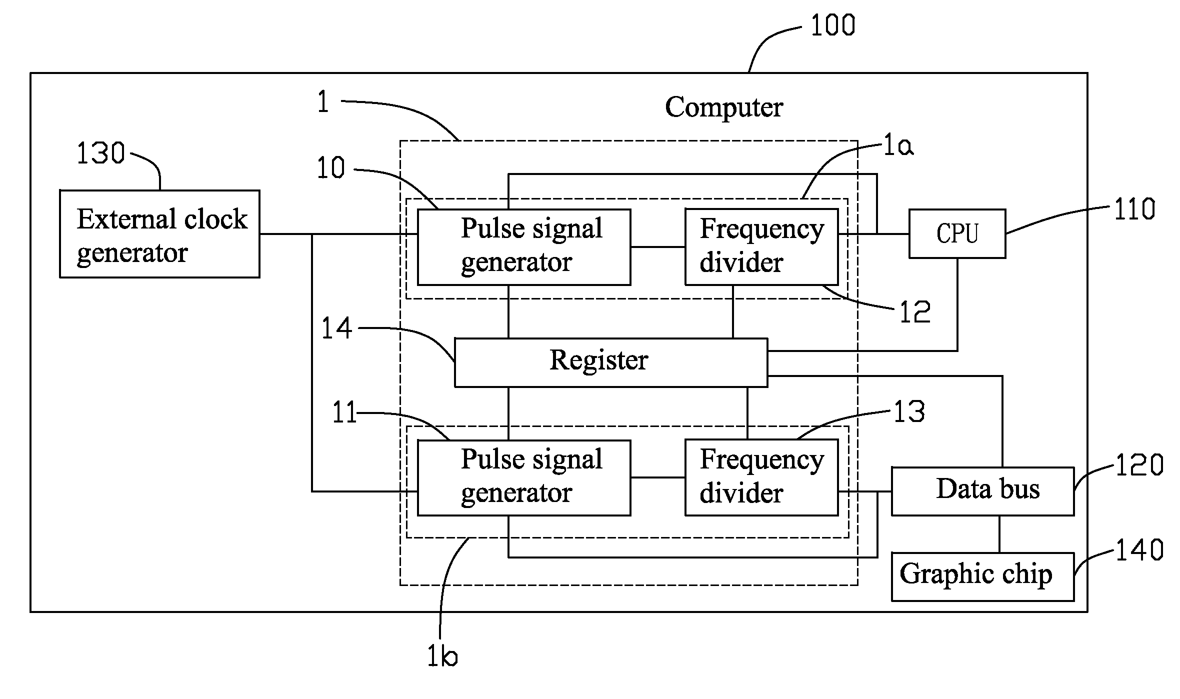
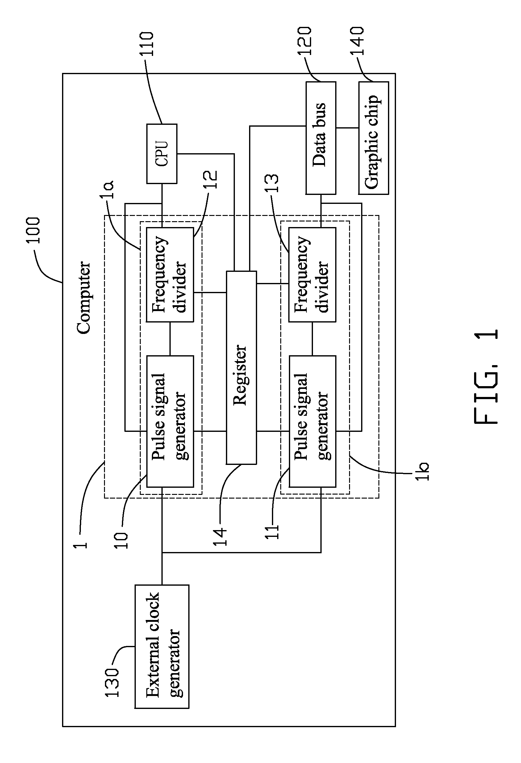
[0007]Referring to FIG. 1, an embodiment of a clock generating circuit 1 is to provide clock signals to components of a computer 100, such as a central processing unit (CPU) 110 and a data bus 120 of the computer 100. The embodiment of the clock generating circuit 1 includes two phase-locked loop (PLL) circuits 1a, 1b, and a register 14. The PLL circuit 1a includes a pulse signal generator 10, and a frequency divider 12 connected between the pulse signal generator 10 and the CPU 110. The PLL circuit 1b includes a pulse signal generator 11, and a frequency divider 13 connected between the pulse signal generator 11 and the data bus 120. The register 14 is connected to the pulse signal generators 10, 11, the frequency dividers 12, 13, the CPU 110, and the data bus 120.

[0008]The pulse signal generators 10, 11 are operable to receive an external clock signal from an external clock generator 130 of the computer 100, and output first and second pulse signals according to the external clock...


PUM


Abstract

A clock signal generating circuit of a computer includes a first phase locked loop (PLL) circuit and a second PLL circuit. The computer includes a central processing unit (CPU) and a data bus. The first PLL provides a CPU clock signal to the CPU. A frequency of the CPU clock signal is the same as a working frequency of the CPU. The second PLL circuit provides a bus clock signal to the data bus. A frequency of bus clock signal is the same as a working frequency of the data bus. The data bus is to communicate with a graphic chip. The CPU clock signal is to control a working speed of the CPU. The bus clock signal is to control a working speed of the data bus.

Description

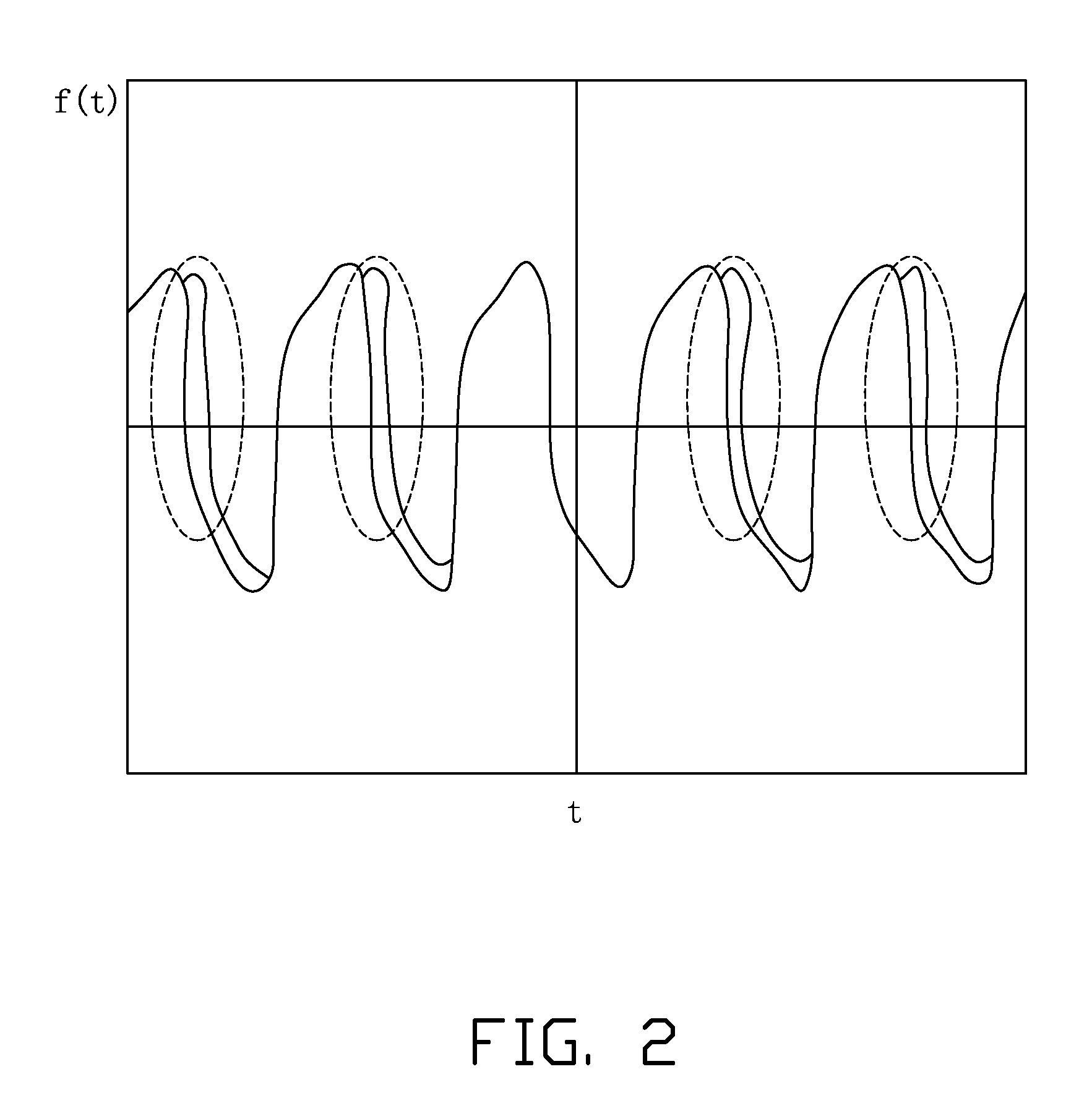
BACKGROUND[0001]1. Technical Field[0002]The present disclosure relates to clock generators, and more particularly to a clock signal generating circuit of a computer.[0003]2. Description of Related Art[0004]Clock generators in computer motherboards of computers are used to provide required clock frequencies to control speeds of computer components, such as main processers, system buses, and various interfaces. Performance of the computers may be influenced if the clock generators are improperly designed. For example, when a Bitland X1550 graphic card works with an Intel E4400 central processing unit in a computer, no image can be displayed, this problem is caused by a deficiently designed clock generator of the computer.BRIEF DESCRIPTION OF THE DRAWINGS[0005]FIG. 1 is a block diagram of an embodiment of a clock generating circuit of a computer.[0006]FIG. 2 is a wave diagram of a clock signal of a computer graphic chip of the computer of FIG. 1, without utilizing the clock generating ...

Claims


Application Information

Patent Timeline
Patent Type & Authority Applications(United States)
IPC IPC(8): G06F1/04
CPCH03L7/23G06F1/08
Inventor HU, KE-YOU
Owner HONG FU JIN PRECISION IND (SHENZHEN) CO LTD
Learn More